POWER DISTRIBUTION POWER MANAGEMENT CONTROL ECU INSTALLATION
PROCEDURE

 89681A
1.INSTALL POWER MANAGEMENT CONTROL ECU
for LHD:
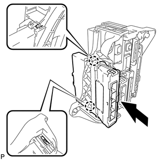
Engage the 2 claws to install the power management control ECU as shown in the illustration.
for RHD:
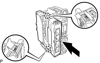
Engage the 2 claws to install the power management control ECU as shown in the illustration.
82877
2.INSTALL ECU INTEGRATION BOX RH (for LHD)
Install the ECU integration box RH with the bolt and 2 nuts.
- Torque:
- Bolt : 8.0 N*m (82 kgf*cm, 71 in.*lbf)
- Nut : 5.5 N*m (56 kgf*cm, 49 in.*lbf)
Engage the 3 clamps.
Connect each connector.
82878
3.INSTALL ECU INTEGRATION BOX LH (for RHD)
Install the ECU integration box LH with the bolt and nut.
- Torque:
- Bolt : 8.0 N*m (82 kgf*cm, 71 in.*lbf)
- Nut : 5.5 N*m (56 kgf*cm, 49 in.*lbf)
Engage the clamp.
Connect each connector.
55550
4.INSTALL GLOVE COMPARTMENT DOOR ASSEMBLY
55607
5.INSTALL NO. 2 INSTRUMENT PANEL UNDER COVER SUB-ASSEMBLY
6.CONNECT CABLE TO NEGATIVE AUXILIARY BATTERY TERMINAL
- NOTICE:
-
When disconnecting the cable, some systems need to be initialized after the cable is reconnected (See page General>INTRODUCTION>REPAIR INSTRUCTION>INITIALIZATION).
64995
7.INSTALL DECK FLOOR BOX RH
64993
8.INSTALL REAR DECK FLOOR BOX
58411A
9.INSTALL NO. 1 DECK BOARD
58412A
10.INSTALL NO. 2 DECK BOARD
58410B
11.INSTALL DECK BOARD ASSEMBLY