RM2070E
_58
Vehicle Interior
_061940
METER / GAUGE / DISPLAY
_0301792
METER / GAUGE SYSTEM
J
METER / GAUGE / DISPLAY METER / GAUGE SYSTEM Entire Combination Meter does not Operate
DESCRIPTION
This circuit is the power source circuit for the meter. This circuit provides two types of power sources; one is a constant power source, and the other is an IG power source.
WIRING DIAGRAM
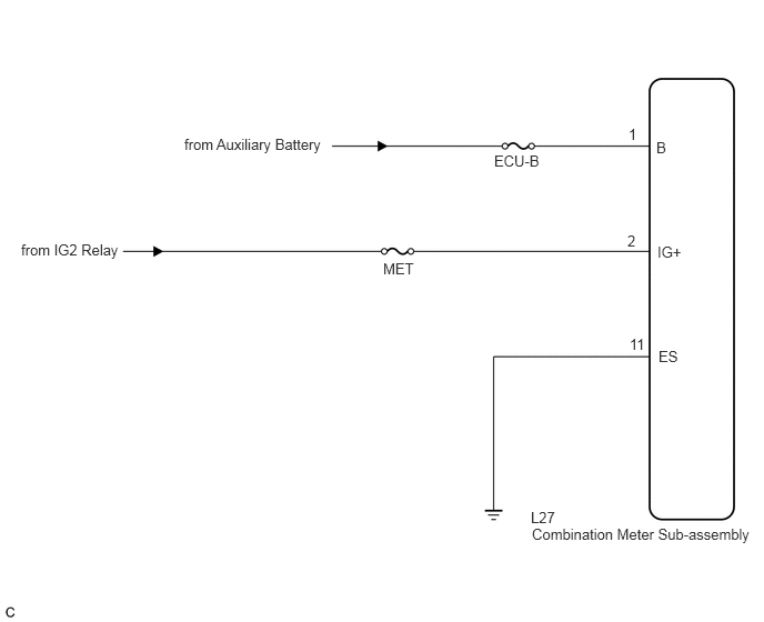
4.99,4.927 7.156,5.229
2.167,0.302
10
false
Combination Meter Sub-assembly
6.156,1.302 6.615,1.583
0.458,0.281
10
false
B
6.167,2.281 6.49,2.51
0.323,0.229
10
false
IG+
6.177,3.26 6.646,3.552
0.469,0.292
10
false
ES
5.896,1.177 6.167,1.333
0.271,0.156
10
false
1
5.885,2.177 6.344,2.531
0.458,0.354
10
false
2
4.979,4.771 5.26,4.927
0.281,0.156
10
false
L27
5.906,3.146 6.104,3.354
0.198,0.208
10
false
11
4.635,1.427 5.365,1.708
0.729,0.281
10
false
ECU-B
3.594,2.438 4.375,2.781
0.781,0.344
10
false
MET
1.729,1.271 3.115,1.802
1.385,0.531
10
false
from Auxiliary Battery
0.198,2.26 1.104,2.677
0.906,0.417
10
false
from IG2 Relay
CAUTION / NOTICE / HINT
- NOTICE:
-
Inspect the fuses of circuits related to this system before performing the following inspection procedure.
PROCEDURE
1.CHECK HARNESS AND CONNECTOR (COMBINATION METER SUB-ASSEMBLY CIRCUIT)
a.
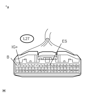
0.198,0.162 0.378,0.325
0.179,0.163
10
*a
0.841,1.315 1.139,1.496
0.298,0.181
10
L27
0.419,1.616 0.670,1.795
0.251,0.178
10
IG+
0.242,1.98 0.364,2.159
0.122,0.178
10
B
0.733,2.354 0.586,1.794
false
0.389,2.099 0.606,2.358
false
2.245,1.408 2.471,1.586
0.225,0.178
10
ES
2.221,1.572 1.804,2.351
false
Disconnect the L27 combination meter sub-assembly connector.
b.
Measure the resistance according to the value(s) in the table below.
- Standard Resistance:
Tester Connection Condition Specified Condition L27-11 (ES) - Body ground Always Below 1 Ω
c.
Measure the voltage according to the value(s) in the table below.
- Standard Voltage:
Tester Connection Condition Specified Condition L27-2 (IG+) - Body ground Power switch off Below 1 V Power switch on (IG) 11 to 14 V L27-1 (B) - Body ground Power switch off 11 to 14 V
| *a | Front view of wire harness connector
(to Combination Meter Sub-assembly) |
| Result | Proceed to |
|---|---|
| OK (w/o Multi-information display) | A |
| OK (w/ Multi-information display) | B |
| NG | C |
A
REPLACE METER CIRCUIT PLATE
B
REPLACE COMBINATION METER SUB-ASSEMBLY
C
REPAIR OR REPLACE HARNESS OR CONNECTOR