SUPPLEMENTAL RESTRAINT SYSTEMS KNEE AIRBAG ASSEMBLY INSTALLATION
PROCEDURE

 73900
1.INSTALL LOWER NO. 1 INSTRUMENT PANEL AIRBAG ASSEMBLY
Check that the power switch is off.
Check that the cable is disconnected from the negative (-) auxiliary battery terminal.
- CAUTION:
-
Wait at least 90 seconds after disconnecting the cable from the negative (-) auxiliary battery terminal to disable the SRS system.
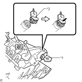
Connect the airbag connector to the lower No. 1 instrument panel airbag assembly.
- NOTICE:
-
When connecting any airbag connector, take care not to damage the airbag wire harness.
Push in the airbag connector lock to install the airbag connector.
| *1 | Airbag Connector |
| *2 | Airbag Connector Lock |
Install the clamp.
for LHD:
Engage the 2 claws to connect the DLC3.
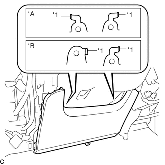
Temporarily install the lower No. 1 instrument panel airbag assembly with the 2 hooks.
| *1 | Hook |
| *A | for RHD |
| *B | for LHD |
Engage the 6 claws and 3 guides to install the lower No. 1 instrument panel airbag assembly.
Install the 4 bolts.
- Torque:
- 10 N*m (102 kgf*cm, 7 ft.*lbf)
- NOTICE:
-
Confirm that the lower No. 1 instrument panel airbag assembly is installed securely without any excessive gaps and is not protruding outward.
55606
2.INSTALL NO. 1 INSTRUMENT PANEL UNDER COVER SUB-ASSEMBLY
3.INSTALL LOWER INSTRUMENT PANEL FINISH PANEL SUB-ASSEMBLY
55480D
4.INSTALL LOWER INSTRUMENT PANEL FINISH PANEL ASSEMBLY
55431B
5.INSTALL UPPER INSTRUMENT PANEL FINISH PANEL
6.INSTALL INTEGRATION CONTROL AND PANEL
58810J
7.INSTALL CONSOLE BOX ASSEMBLY
8.CONNECT CABLE TO NEGATIVE AUXILIARY BATTERY TERMINAL
- NOTICE:
-
When disconnecting the cable, some systems need to be initialized after the cable is reconnected (See page General>INTRODUCTION>REPAIR INSTRUCTION>INITIALIZATION).
64995
9.INSTALL DECK FLOOR BOX RH
64993
10.INSTALL REAR DECK FLOOR BOX
58411A
11.INSTALL NO. 1 DECK BOARD
58412A
12.INSTALL NO. 2 DECK BOARD
58410B
13.INSTALL DECK BOARD ASSEMBLY
14. PERFORM DIAGNOSTIC SYSTEM CHECK
15.INSPECT SRS WARNING LIGHT