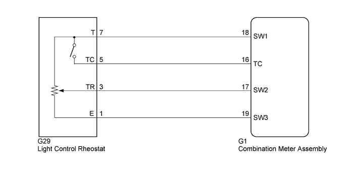
METER / GAUGE SYSTEM > Operating Light Control Rheostat does not Change Light Brightness |
| 1.SYSTEM CHECK |
Confirm the symptoms.
| Result | Proceed to |
| Meter illumination does not change when operating the light control rheostat. | A |
| Dimmer function cannot be canceled. | B |
|
| ||||
| A | |
 |
| 2.READ VALUE USING TECHSTREAM (RHEOSTAT VALUE) |
Connect the Techstream to the DLC3.
Turn the power switch on (IG).
Turn the Techstream on.
Enter the following menus: Body Electrical / Combination Meter / Data List.
Check the values by referring to the table below.
| Tester Display | Measurement Item/Range | Normal Condition | Diagnostic Note |
| Rheostat value | Light control rheostat/Min.: 0 (dark), Max.: 100 (bright) | Light control rheostat value 0 (dark) | The value changes with rheostat operation |
| Light control rheostat value 100 (bright) |
|
| ||||
| OK | ||
 | ||
| ||
| 3.INSPECT LIGHT CONTROL RHEOSTAT |
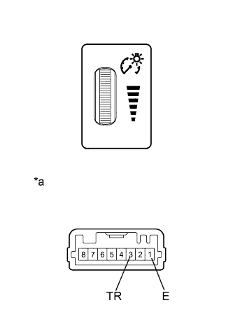 |
Remove the light control rheostat (Click here).
Measure the resistance according to the value(s) in the table below.
| Tester Connection | Condition | Specified Condition |
| 1 (E) - 3 (TR) | Light control rheostat is fully turned downwards (MIN.) | Below 50 Ω |
| Light control rheostat position is between MIN. and MAX. | The value changes gradually (Between 0 to 12 kΩ) | |
| Light control rheostat is fully turned upwards (MAX.) | 8 to 12 kΩ |
| *a | Component without harness connected (Light Control Rheostat) |
|
| ||||
| OK | |
|
| 4.CHECK HARNESS AND CONNECTOR (COMBINATION METER ASSEMBLY - LIGHT CONTROL RHEOSTAT) |
Disconnect the G1 combination meter assembly connector.
Disconnect the G29 light control rheostat connector.
Measure the resistance according to the value(s) in the table below.
| Tester Connection | Condition | Specified Condition |
| G1-17 (SW2) - G29-3 (TR) | Always | Below 1 Ω |
| G1-17 (SW2) - Body ground | Always | 10 kΩ or higher |
| G1-19 (SW3) - G29-1 (E) | Always | Below 1 Ω |
| G1-19 (SW3) - Body ground | Always | 10 kΩ or higher |
|
| ||||
| OK | ||
| ||
| ||
| 5.READ VALUE USING TECHSTREAM (TAIL CANCEL SW) |
Connect the Techstream to the DLC3.
Turn the power switch on (IG).
Turn the Techstream on.
Enter the following menus: Body Electrical / Combination Meter / Data List.
Check the values by referring to the table below.
| Tester Display | Measurement Item/Range | Normal Condition | Diagnostic Note |
| Tail Cancel SW | Tail cancel switch/OFF or ON | OFF: Tail cancel switch off | Dimming of dash lights is possible |
| ON: Tail cancel switch on | Dimming of dash lights is canceled |
|
| ||||
| OK | ||
| ||
| ||
| 6.INSPECT LIGHT CONTROL RHEOSTAT |
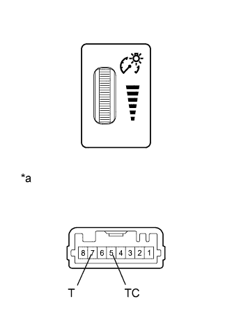 |
Remove the light control rheostat (Click here).
Measure the resistance according to the value(s) in the table below.
| Tester Connection | Condition | Specified Condition |
| 5 (TC) - 7 (T) | Light control rheostat position is not fully turned upwards (Tail cancel switch is off) | Below 50 Ω |
| Light control rheostat is fully turned upwards (Tail cancel switch is on) | 8 to 12 kΩ |
| *a | Component without harness connected (Light Control Rheostat) |
|
| ||||
| OK | |
|
| 7.CHECK HARNESS AND CONNECTOR (COMBINATION METER ASSEMBLY - LIGHT CONTROL RHEOSTAT) |
Disconnect the G1 combination meter assembly connector.
Disconnect the G29 light control rheostat connector.
Measure the resistance according to the value(s) in the table below.
| Tester Connection | Condition | Specified Condition |
| G1-18 (SW1) - G29-7 (T) | Always | Below 1 Ω |
| G1-18 (SW1) - Body ground | Always | 10 kΩ or higher |
| G1-16 (TC) - G29-5 (TC) | Always | Below 1 Ω |
| G1-16 (TC) - Body ground | Always | 10 kΩ or higher |
|
| ||||
| OK | ||
| ||
| ||

