Home › Engine / Hybrid System › HYBRID / BATTERY CONTROL › HYBRID BATTERY SYSTEM

DTC    P0A9C-123    Hybrid Battery Temperature Sensor "A" Range / Performance

DTC    P0AC6-123    Hybrid Battery Temperature Sensor "B" Range / Performance

DTC    P0ACB-123    Hybrid Battery Temperature Sensor "C" Range / Performance

DTC    P3065-123    Hybrid Battery Temperature Sensor Range/Performance Stuck "A"

for Preparation Click here


DESCRIPTION


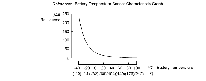
  1. The battery temperature sensors are provided at 3 locations of the HV battery. The resistance of the thermistor, which is built into each battery temperature sensor, varies in accordance with changes in the HV battery temperature. The lower the battery temperature, the higher the thermistor resistance. Conversely, the higher the temperature, the lower the resistance. The battery smart unit uses the battery temperature sensors to detect the HV battery temperature, and sends the detected value to the power management control ECU. Based on the results of this detection, the power management control ECU controls the blower fan. (The blower fan starts when HV battery temperature rises above a predetermined level.)

    Temperature Sensor Identification Cross Reference Table:
    DTC Title Sensor
    Battery Temperature Sensor
    Techstream Display
    A
    0
    1
    B
    1
    2
    C
    2
    3

    HINT:
    For example, sensor A in the DTC title is battery temperature sensor (No. 0). This sensor is displayed as Temp of Batt TB1 in the Data List.


    A171806E02


DTC No.
INF Code
DTC Detection Condition
Trouble Area
P0A9C
123
The performance of battery temperature sensor 0 is abnormal and its output is stuck.
(2 trip detection logic)
  1. HV battery
  2. Battery smart unit
  3. Wire harness or connector
P0AC6
123
The performance of battery temperature sensor 1 is abnormal and its output is stuck.
(2 trip detection logic)
P0ACB
123
The performance of battery temperature sensor 2 is abnormal and its output is stuck.
(2 trip detection logic)
P3065
123
The performance of any battery temperature sensor is abnormal, the difference in output between it and other battery temperature sensors is excessively large.
(1 trip detection logic)

Related Data List 
DTC No.
Data List
P0A9C-123
P0AC6-123
P0ACB-123
P3065-123
Temp of Batt TB1 to 3
The following items can be helpful when performing repairs:
Data List
  1. Vehicle Spd
  2. Ambient Temperature

MONITOR DESCRIPTION

If the battery smart unit detects a malfunction in the HV battery temperature sensor, the power management control ECU illuminates the MIL and set a DTC.

MONITOR STRATEGY


Related DTCs
P0A9C (INF 123): Battery temperature sensor malfunction (stuck)
P0AC6 (INF 123): Battery temperature sensor malfunction (stuck)
P0ACB (INF 123): Battery temperature sensor malfunction (stuck)
P3065 (INF 123): Battery temperature sensor malfunction (deviation)
Required sensors / components
Battery temperature sensor
Frequency of operation
Continuous
Duration
TMC's intellectual property
MIL operation
TMC's intellectual property
Sequence of operation
None

TYPICAL ENABLING CONDITIONS


The monitor will run whenever the following DTCs are not present
TMC's intellectual property
Other conditions belong to TMC's intellectual property
-

TYPICAL MALFUNCTION THRESHOLDS


TMC's intellectual property
-

COMPONENT OPERATING RANGE


Battery smart unit
DTC P0A9C (INF 123) is not detected
DTC P0AC6 (INF 123) is not detected
DTC P0ACB (INF 123) is not detected
DTC P3065 (INF 123) is not detected

CONFIRMATION DRIVING PATTERN


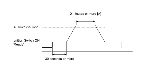
A308330E01

  1. Connect the Techstream to the DLC3.
  2. Turn the ignition switch to ON (IG) and turn the Techstream on.
  3. Clear the DTCs (even if no DTCs are stored, perform the clear DTC procedure).
  4. Turn the ignition switch off and wait for 30 seconds or more.
  5. Turn the ignition switch to ON (IG) and turn the Techstream on.
  6. Turn the ignition switch to ON (READY).
  7. Check that the temperature of each temperature sensor is -10°C (14°F) or more.

    HINT:
    If any of temperature sensor values are less than -10°C (14°F), raise the temperature to -10°C (14°F) or more and then perform the next step.

  8. Turn the ignition switch to ON (READY) and wait for 30 seconds or more.

    HINT:
    Check that there are no abnormalities. (abnormal sounds, coolant leaks, DTC output, etc.)

  9. Drive the vehicle on urban roads at a speed of 40 km/h (25 mph) or more for a total of at least 10 minutes. [A]

    NOTICE:
    Avoid abrupt acceleration or braking.

  10. Enter the following menus: Powertrain / Hybrid Control / Trouble Codes.
  11. Read the pending DTCs. (DTC P0A9C-123, P0AC6-123, P0ACB-123)

    HINT:
    1. If a pending DTC is output, the system is malfunctioning.
    2. If a pending DTC is not output, perform the following procedure.

  12. Read the current DTCs. (DTC P3065-123)

    HINT:
    1. If a current DTC is output, the system is malfunctioning.
    2. If a current DTC is not output, perform the following procedure.

  13. Check that permanent DTCs are cleared. If no permanent DTC is output, the system is normal.
  14. If the permanent DTCs are not cleared, perform the universal trip, and then check for permanent DTCs again.

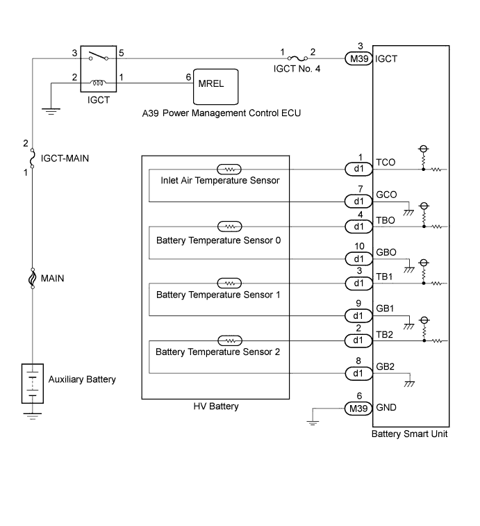
WIRING DIAGRAM


A244328E02


INSPECTION PROCEDURE

CAUTION:
  1. Before inspecting the high-voltage system, take safety precautions to prevent electrical shocks, such as wearing insulated gloves and removing the service plug grip. After removing the service plug grip, put it in your pocket to prevent other technicians from accidentally reconnecting it while you are working on the high-voltage system.
  2. After removing the service plug grip, wait for at least 10 minutes before touching any of the high-voltage connectors or terminals. After waiting for 10 minutes, check the voltage at the terminals in the inspection point in the inverter with converter assembly. The voltage should be 0 V before beginning work (Click here).

    HINT:
    At least 10 minutes is required to discharge the high-voltage capacitor inside the inverter with converter assembly.

  3. When disposing of an HV battery, make sure to return it through an authorized collection agent who is capable of handling it safely. If the HV battery is returned via the manufacturer specified route, it will be returned properly and in a safe manner by an authorized collection agent.

NOTICE:
After turning the ignition switch off, waiting time may be required before disconnecting the cable from the negative (-) auxiliary battery terminal. Therefore, make sure to read the disconnecting the cable from the negative (-) auxiliary battery terminal notices before proceeding with work (Click here).

HINT:
  1. If DTC P0A9C-123, P0AC6-123 or P0ACB-123 is output, clear the DTCs, perform the following procedure, and check that the same DTC (including pending DTC) is not output after the repair.
    1. Drive the vehicle for approximately 10 minutes according to the freeze frame data items "Vehicle Spd", "Accelerator Degree", "Temp of Batt TB1 to TB3" and "Power Resource IB".
      1. Check that the output of each battery temperature sensor varies.
      2. Check that the difference in output between each battery temperature sensor is not excessively large.
  2. If DTC P3065-123 is output, clear the DTCs, perform the following procedure, and check that the same DTC is not output after the repair.
    1. Turn the ignition switch to ON (IG) and wait for 10 seconds or more.
      Check that the difference in output between each battery temperature sensor is not excessively large.

1.CHECK DTC OUTPUT (HYBRID CONTROL)
  1. Connect the Techstream to the DLC3.

  1. Turn the ignition switch to ON (IG).

  1. Enter the following menus: Powertrain / Hybrid Control / Trouble Codes.

  1. Check and record any HV system DTCs, INF codes and freeze frame data.

  1. Read output DTCs (Click here).

    Result:
    Result
    Proceed to
    P0AFC-123 is not output.
    A
    P0AFC-123 is also output.
    B

  1. Turn the ignition switch off.

  1. Disconnect the Techstream from the DLC3.


B
GO TO DTC CHART (P0AFC-123) (Click here)
A


2.CHECK INSTALLATION OF BATTERY TEMPERATURE SENSOR

CAUTION:
Be sure to wear insulated gloves and protective goggles.

  1. Check that the service plug grip is not installed.

    NOTICE:
    After removing the service plug grip, do not turn the ignition switch to ON (READY), unless instructed by the repair manual because this may cause a malfunction.

  1. Remove the upper hybrid battery cover sub-assembly .


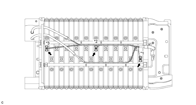
  1. Visually check the installation condition of the relevant battery temperature sensor.


    A266554E01

    Standard Condition:
    Each battery temperature sensor is installed in the correct location with the correct orientation and its claws are engaged securely.

    Result:
    Result
    Proceed to
    Each battery temperature sensor is installed in the correct location with the correct orientation and its claws are engaged securely
    A
    Claws are damaged.
    B
    Any of battery temperature sensors are not installed correctly, but claws are not damaged.
    C

    NOTICE:
    Do not use a stick or similar object to push on the sensors when inspecting them. Doing so may result in damage to the sensors.


    Text in Illustration 
    *1
    Battery Temperature Sensor 0
    *2
    Battery Temperature Sensor 1
    *3
    Battery Temperature Sensor 2
    -
    -

  1. Install the upper hybrid battery cover sub-assembly.


B
REPLACE HV BATTERY (Click here)

C
INSTALL PARTS CORRECTLY
A


3.CHECK HV BATTERY (BATTERY TEMPERATURE SENSOR)

CAUTION:
Be sure to wear insulated gloves.

  1. Check that the service plug grip is not installed.

    NOTICE:
    After removing the service plug grip, do not turn the ignition switch to ON (READY), unless instructed by the repair manual because this may cause a malfunction.

  1. Remove the No. 1 hybrid battery shield sub-assembly .

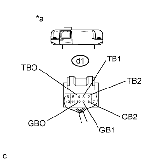
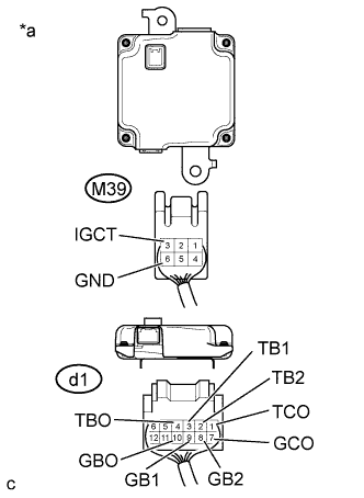
  1. Disconnect connectors d1 and M39 from the battery smart unit.


    A260171E02
  1. Measure the resistance of the circuit for the malfunctioning sensor (battery temperature sensor 0 to 2).
    Tester Connection 
    Tester Connection
    Battery Temperature Sensor No.
    d1-4 (TBO) - d1-10 (GBO)
    0
    d1-3 (TB1) - d1-9 (GB1)
    1
    d1-2 (TB2) - d1-8 (GB2)
    2

    Standard Resistance:
    Thermistor Temperature
    Switch Condition
    Specified Condition
    0°C (32°F)
    Ignition switch off
    26.7 to 27.8 kΩ
    25°C (77°F)
    Ignition switch off
    9.9 to 10.1 kΩ
    40°C (104°F)
    Ignition switch off
    5.73 to 5.92 kΩ

    Text in Illustration 
    *a
    Rear view of wire harness connector
    (to Battery Smart Unit)


    A244309E06
  1. Measure the resistance according to the value(s) in the table below.

    Standard Resistance:
    Tester Connection
    Switch Condition
    Standard Resistance
    d1-4 (TBO) - M39-3 (IGCT)
    Ignition switch off
    10 kΩ or more
    d1-4 (TBO) - M39-6 (GND)
    Ignition switch off
    10 kΩ or more
    d1-10 (GBO) - M39-3 (IGCT)
    Ignition switch off
    10 kΩ or more
    d1-10 (GBO) - M39-6 (GND)
    Ignition switch off
    10 kΩ or more
    d1-3 (TB1) - M39-3 (IGCT)
    Ignition switch off
    10 kΩ or more
    d1-3 (TB1) - M39-6 (GND)
    Ignition switch off
    10 kΩ or more
    d1-9 (GB1) - M39-3 (IGCT)
    Ignition switch off
    10 kΩ or more
    d1-9 (GB1) - M39-6 (GND)
    Ignition switch off
    10 kΩ or more
    d1-2 (TB2) - M39-3 (IGCT)
    Ignition switch off
    10 kΩ or more
    d1-2 (TB2) - M39-6 (GND)
    Ignition switch off
    10 kΩ or more
    d1-8 (GB2) - M39-3 (IGCT)
    Ignition switch off
    10 kΩ or more
    d1-8 (GB2) - M39-6 (GND)
    Ignition switch off
    10 kΩ or more
    d1-1 (TCO) - M39-3 (IGCT)
    Ignition switch off
    10 kΩ or more
    d1-1 (TCO) - M39-6 (GND)
    Ignition switch off
    10 kΩ or more
    d1-7 (GCO) - M39-3 (IGCT)
    Ignition switch off
    10 kΩ or more
    d1-7 (GCO) - M39-6 (GND)
    Ignition switch off
    10 kΩ or more

    Text in Illustration 
    *a
    Rear view of wire harness connector
    (to Battery Smart Unit)

  1. Connect the battery smart unit connectors.

  1. Install the No. 1 hybrid battery shield sub-assembly.


NG
Go to step 4
OK

REPLACE BATTERY SMART UNIT (Click here)  

4.CHECK HARNESS AND CONNECTOR (BATTERY TEMPERATURE SENSOR)

CAUTION:
Be sure to wear insulated gloves and protective goggles.

  1. Check that the service plug grip is not installed.

    NOTICE:
    After removing the service plug grip, do not turn the ignition switch to ON (READY), unless instructed by the repair manual because this may cause a malfunction.

  1. Remove the upper hybrid battery cover sub-assembly .

  1. Check the wire harness and connectors of the battery temperature sensor for abnormalities by sight and touch.

    Specified Condition:
    There are no open or short circuits in the wire harness and connectors. There are no short circuits to other wire harnesses.

HINT:
Because the battery harness is not available as a supply part, if the harness cannot be repaired, replace the HV battery assembly.

  1. Install the upper hybrid battery cover sub-assembly.


NG
REPAIR HARNESS OR CONNECTOR (BATTERY TEMPERATURE SENSOR)
OK

REPLACE HV BATTERY (Click here)