| B |  |
| GO TO DTC CHART (P0AFC-123) (Click here) |
DTC P0A9D-123 Hybrid Battery Temperature Sensor "A" Circuit Low |
DTC P0A9E-123 Hybrid Battery Temperature Sensor "A" Circuit High |
DTC P0AC7-123 Hybrid Battery Temperature Sensor "B" Circuit Low |
DTC P0AC8-123 Hybrid Battery Temperature Sensor "B" Circuit High |
DTC P0ACC-123 Hybrid Battery Temperature Sensor "C" Circuit Low |
DTC P0ACD-123 Hybrid Battery Temperature Sensor "C" Circuit High |
| DTC No. | INF Code | DTC Detection Condition | Trouble Area |
| P0A9D P0AC7 P0ACC | 123 | The battery temperature sensor is malfunctioning, its output voltage is lower than the specified value (short circuit) and the detected temperature is higher than the specified value. (1 trip detection logic) |
|
| P0A9E P0AC8 P0ACD | The battery temperature sensor is malfunctioning, its output voltage is higher than the specified value (short to +B or open) and the detected temperature is lower than the specified value. (1 trip detection logic) |
| Temperature Displayed | Malfunction |
| Below -45°C (-49°F) | Open or +B short circuit |
| 95°C (203°F) or more | GND short circuit |
| DTC No. | Data List |
| P0A9D-123 P0A9E-123 P0AC7-123 P0AC8-123 P0ACC-123 P0ACD-123 | Temp of Batt TB1 to TB3 |
| Related DTCs | P0A9D (INF 123): Battery temperature sensor circuit malfunction (GND short) P0A9E (INF 123): Battery temperature sensor circuit malfunction (open) P0AC7 (INF 123): Battery temperature sensor circuit malfunction (GND short) P0AC8 (INF 123): Battery temperature sensor circuit malfunction (open) P0ACC (INF 123): Battery temperature sensor circuit malfunction (GND short) P0ACD (INF 123): Battery temperature sensor circuit malfunction (open) |
| Required sensors / components | Battery temperature sensor |
| Frequency of operation | Continuous |
| Duration | TMC's intellectual property |
| MIL operation | TMC's intellectual property |
| Sequence of operation | None |
| The monitor will run whenever the following DTCs are not present | TMC's intellectual property |
| Other conditions belong to TMC's intellectual property | - |
| TMC's intellectual property | - |
| Battery smart unit | DTC P0A9D (INF 123) is not detected DTC P0A9E (INF 123) is not detected DTC P0AC7 (INF 123) is not detected DTC P0AC8 (INF 123) is not detected DTC P0ACC (INF 123) is not detected DTC P0ACD (INF 123) is not detected |
| 1.CHECK DTC OUTPUT (HYBRID CONTROL) |
Connect the Techstream to the DLC3.
Turn the ignition switch to ON (IG).
Enter the following menus: Powertrain / Hybrid Control / Trouble Codes.
Check and record any HV system DTCs, INF codes and freeze frame data.
Read output DTCs (Click here).
| Result | Proceed to |
| P0AFC-123 is not output. | A |
| P0AFC-123 is also output. | B |
Turn the ignition switch off.
Disconnect the Techstream from the DLC3.
|
| ||||
| A | |
 |
| 2.READ VALUE USING TECHSTREAM |
Connect the Techstream to the DLC3.
Turn the ignition switch to ON (IG).
Enter the following menus: Powertrain / Hybrid Control / Data List / Temp of Batt TB 1 to 3.
Turn the ignition switch off.
| NEXT | |
|
| 3.CHECK CONNECTOR CONNECTION CONDITION |
Check that the service plug grip is not installed.
Remove the No. 1 hybrid battery shield sub-assembly .
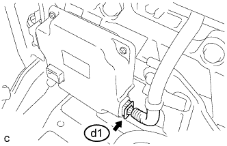 |
Check the connections of the d1 connector of the battery smart unit.
Install the No. 1 hybrid battery shield sub-assembly.
|
| ||||
| OK | |
|
| 4.CHECK HV BATTERY (BATTERY TEMPERATURE SENSOR) |
Check that the service plug grip is not installed.
Remove the No. 1 hybrid battery shield sub-assembly .
Disconnect connectors d1 and M39 from the battery smart unit.
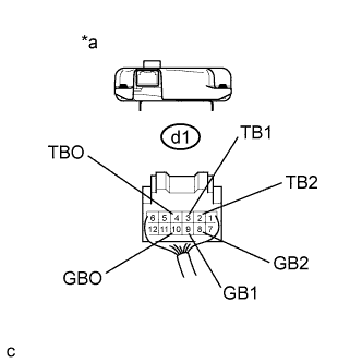 |
Measure the resistance of the circuit for the malfunctioning sensor (battery temperature sensor 0 to 2).
| Tester Connection | Battery Temperature Sensor No. |
| d1-4 (TBO) - d1-10 (GBO) | 0 |
| d1-3 (TB1) - d1-9 (GB1) | 1 |
| d1-2 (TB2) - d1-8 (GB2) | 2 |
| Thermistor Temperature | Switch Condition | Specified Condition |
| 0°C (32°F) | Ignition switch off | 26.7 to 27.8 kΩ |
| 25°C (77°F) | Ignition switch off | 9.9 to 10.1 kΩ |
| 40°C (104°F) | Ignition switch off | 5.73 to 5.92 kΩ |
| *a | Rear view of wire harness connector (to Battery Smart Unit) |
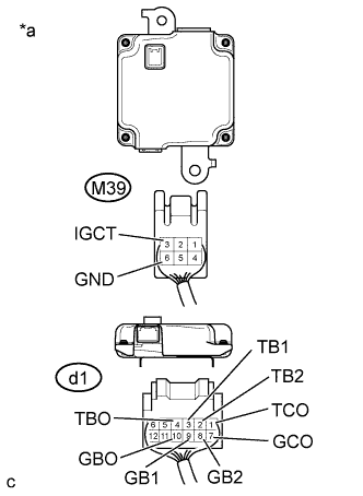 |
Measure the resistance according to the value(s) in the table below.
| Tester Connection | Switch Condition | Standard Resistance |
| d1-4 (TBO) - M39-3 (IGCT) | Ignition switch off | 10 kΩ or more |
| d1-4 (TBO) - M39-6 (GND) | Ignition switch off | 10 kΩ or more |
| d1-10 (GBO) - M39-3 (IGCT) | Ignition switch off | 10 kΩ or more |
| d1-10 (GBO) - M39-6 (GND) | Ignition switch off | 10 kΩ or more |
| d1-3 (TB1) - M39-3 (IGCT) | Ignition switch off | 10 kΩ or more |
| d1-3 (TB1) - M39-6 (GND) | Ignition switch off | 10 kΩ or more |
| d1-9 (GB1) - M39-3 (IGCT) | Ignition switch off | 10 kΩ or more |
| d1-9 (GB1) - M39-6 (GND) | Ignition switch off | 10 kΩ or more |
| d1-2 (TB2) - M39-3 (IGCT) | Ignition switch off | 10 kΩ or more |
| d1-2 (TB2) - M39-6 (GND) | Ignition switch off | 10 kΩ or more |
| d1-8 (GB2) - M39-3 (IGCT) | Ignition switch off | 10 kΩ or more |
| d1-8 (GB2) - M39-6 (GND) | Ignition switch off | 10 kΩ or more |
| d1-1 (TCO) - M39-3 (IGCT) | Ignition switch off | 10 kΩ or more |
| d1-1 (TCO) - M39-6 (GND) | Ignition switch off | 10 kΩ or more |
| d1-7 (GCO) - M39-3 (IGCT) | Ignition switch off | 10 kΩ or more |
| d1-7 (GCO) - M39-6 (GND) | Ignition switch off | 10 kΩ or more |
| *a | Rear view of wire harness connector (to Battery Smart Unit) |
Connect the battery smart unit connectors.
Install the No. 1 hybrid battery shield sub-assembly.
|
| ||||
| OK | ||
 | ||
| ||
| 5.CHECK HARNESS AND CONNECTOR (BATTERY TEMPERATURE SENSOR) |
Check that the service plug grip is not installed.
Remove the upper hybrid battery cover sub-assembly .
Check the wire harness and connectors of the battery temperature sensor for abnormalities by sight and touch.
Install the upper hybrid battery cover sub-assembly.
|
| ||||
| OK | ||
| ||
| ||
