ENGINE ASSEMBLY > REMOVAL |
| 1. PRECAUTION |
| 2. RECOVER REFRIGERANT FROM REFRIGERATION SYSTEM |
Start the hybrid system.
Operate the cooler compressor under the conditions show below:
| Item | Condition |
| Engine Speed | Idling |
| Operating Time | 3 minutes or more |
| A/C Switch Status | ON |
| Blower Switch Status | HI |
| Set Temperature | MAX COOL |
Stop the engine.
Recover the refrigerant from the A/C system using a refrigerant recovery unit.
| 3. DISCHARGE FUEL SYSTEM PRESSURE |
| 4. REMOVE SERVICE PLUG GRIP |
| 5. DISCONNECT CABLE FROM NEGATIVE AUXILIARY BATTERY TERMINAL |
| 6. REMOVE ENGINE UNDER COVER LH |
| 7. REMOVE ENGINE UNDER COVER RH |
| 8. DRAIN ENGINE OIL |
Remove the oil filler cap.
Remove the oil pan drain plug and gasket, and drain the oil into a container.
Clean and install the oil drain plug with a new gasket.
| 9. DRAIN COOLANT (for Engine) |
Loosen the radiator drain cock plug.
Remove the water filler cap sub-assembly and drain the coolant.
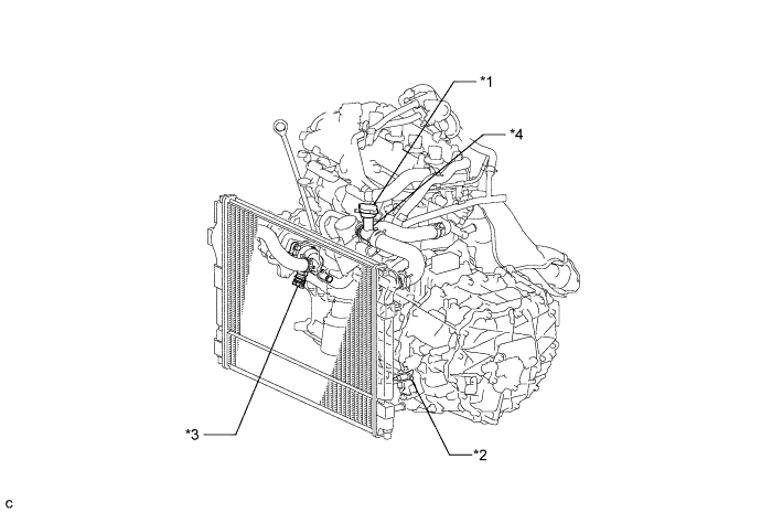
| *1 | Water Filler Cap Sub-assembly | *2 | Radiator Drain Cock Plug |
| *3 | Engine Drain Cock Plug | *4 | Water Filler |
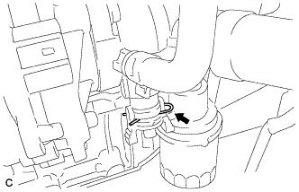
![]() |
Remove the stop ring.
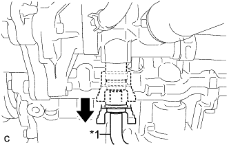
![]() |
Connect the hose to the engine drain cock plug.
| *1 | Hose |
Pull out the engine drain cock plug and drain the coolant.
| 10. DRAIN COOLANT (for Inverter) |
Remove the reserve tank cap.
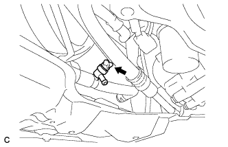
![]() |
Loosen the radiator drain cock plug and drain the coolant.
Tighten the radiator drain cock plug.
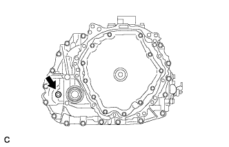
| 11. DRAIN HYBRID TRANSAXLE FLUID |
![]() |
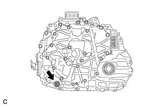
Using a 10 mm hexagon socket wrench, remove the filler plug and gasket.
![]() |
Using a 10 mm hexagon socket wrench, remove the drain plug and gasket to drain the hybrid transaxle fluid.
Using a 10 mm hexagon socket wrench, install the drain plug and a new gasket.
| 12. REMOVE WINDSHIELD WIPER MOTOR AND LINK ASSEMBLY |
| 13. REMOVE INNER COWL TOP TO COWL BRACE |
![]() |
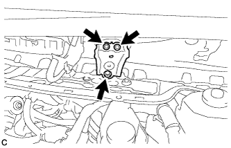
Remove the 3 bolts and inner cowl top to cowl brace.
| 14. REMOVE FRONT AIR SHUTTER SEAL |
![]() |
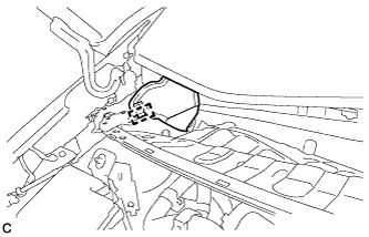
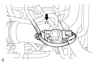
Disengage the clamp to remove the front air shutter seal.
| 15. REMOVE FRONT NO. 1 VENTILATOR SEAL |
![]() |
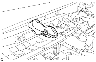
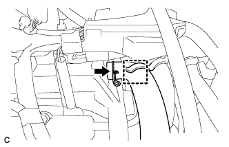
Disengage the clamp to remove the front No. 1 ventilator seal.
| 16. REMOVE OUTER COWL TOP PANEL SUB-ASSEMBLY |
![]() |
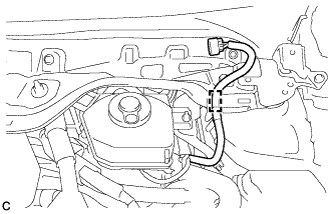
Disengage the clamp to separate the wire harness from the outer cowl top panel sub-assembly.
![]() |
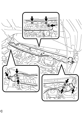
Remove the 8 bolts, nut and outer cowl top panel sub-assembly.
| 17. REMOVE INVERTER WITH CONVERTER ASSEMBLY |
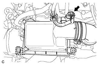
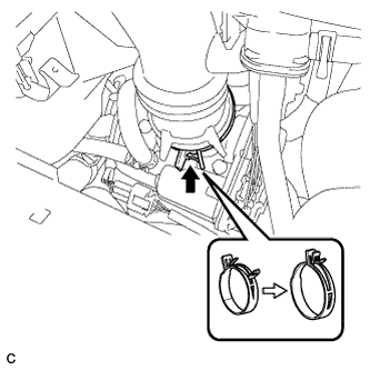
| 18. REMOVE AIR CLEANER CAP SUB-ASSEMBLY |
![]() |
Disconnect the ventilation hose.
![]() |
Disconnect the purge VSV.
![]() |
Disconnect the mass air flow meter connector.
Disconnect the wire harness clamp.
Release the 2 clamps.
![]() |
Loosen the hose clamp and remove the air cleaner cap sub-assembly.
| 19. REMOVE AIR CLEANER CASE SUB-ASSEMBLY |
Remove the air cleaner filter element sub-assembly.
![]() |
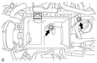
Remove the 2 bolts, grommet and air cleaner case sub-assembly.
| 20. REMOVE INVERTER BRACKET ASSEMBLY |
![]() |
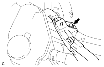
Remove the bolt and separate the motor cable protector.
![]() |
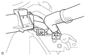
Disconnect the 2 wire harness clamps.
![]() |
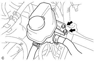
Remove the 2 bolts and separate the inverter reservoir tank assembly.
![]() |
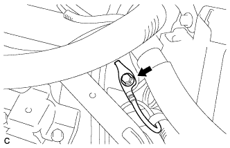
Remove the bolt and disconnect the earth wire.
![]() |
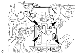
Remove the 4 bolts and inverter bracket assembly.
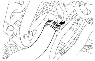
| 21. DISCONNECT NO. 1 RADIATOR HOSE |
![]() |
Disconnect the No. 1 radiator hose from the engine assembly.
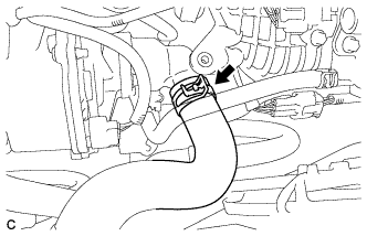
| 22. DISCONNECT NO. 2 RADIATOR HOSE |
![]() |
Disconnect the No. 2 radiator hose from the engine assembly.
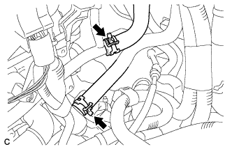
| 23. DISCONNECT HEATER WATER HOSE |
![]() |
Disconnect the 2 heater water hoses from the engine assembly.
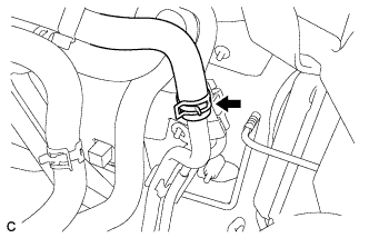
| 24. DISCONNECT FUEL VAPOR FEED HOSE ASSEMBLY |
![]() |
Disconnect the fuel vapor feed hose assembly.
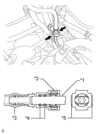
| 25. DISCONNECT FUEL TUBE SUB-ASSEMBLY |
![]() |
Pinch the retainer of the fuel tube connector, and then pull the fuel tube connector off of the fuel delivery pipe.
| *1 | Fuel delivery pipe |
| *2 | Fuel Tube Connector |
| *3 | Nylon Tube |
| *4 | O-ring |
| *5 | Retainer |
![]() | Pinch |
![]() | Pull |
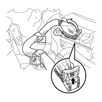
| 26. DISCONNECT ENGINE WIRE |
![]() |
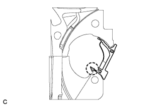
Push the lock on the lever, then raise the lever, and disconnect the ECM connector.
Disconnect the 2 wire harness clamps.
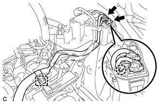
![]() |
Disconnect the 2 connectors and wire harness clamp.
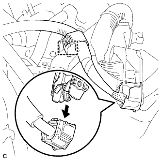
Using a screwdriver, disengage the claw and disconnect the engine wire from the engine room relay block and junction block assembly.
![]() |
Disconnect the engine wire from the engine room main wire.
Disconnect the wire harness clamp.
| 27. DISCONNECT TRANSMISSION CONTROL CABLE ASSEMBLY |
![]() |
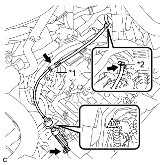
Remove the nut, clip and disconnect the transmission control cable assembly from the No. 1 transmission control cable bracket and transmission control shaft lever.
| *1 | Transmission Control Cable Clamp |
| *2 | Transmission Control Cable Support |
Disconnect the transmission control cable assembly from the transmission control cable clamp and transmission control cable support.
| 28. PLACE FRONT WHEELS FACING STRAIGHT AHEAD |
| 29. SECURE STEERING WHEEL |
![]() |
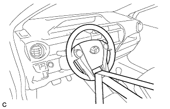
Secure the steering wheel with the seat belt in order to prevent rotation.
| 30. REMOVE COLUMN HOLE COVER SILENCER SHEET |
![]() |
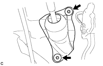
Remove the 2 clips and the column hole cover silencer sheet.
| 31. REMOVE STEERING SLIDING YOKE SUB-ASSEMBLY |
![]() |
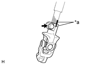
Put matchmarks on the steering sliding yoke sub-assembly and No. 2 steering intermediate shaft assembly.
| *a | Matchmark |
Remove the steering sliding yoke sub-assembly from the No. 2 steering intermediate shaft assembly.
| 32. SEPARATE NO. 1 STEERING COLUMN HOLE COVER SUB-ASSEMBLY |
![]() |
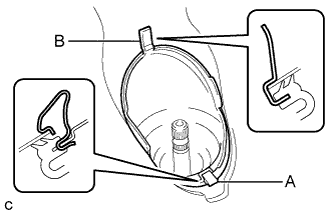
Remove clip A, detach clip B from the body and disconnect the No. 1 steering column hole cover sub-assembly.
| 33. DISCONNECT NO. 1 COOLER REFRIGERANT DISCHARGE HOSE |
![]() |
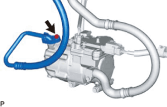
Remove the bolt and disconnect the No. 1 cooler refrigerant discharge hose from the compressor with motor assembly.
Remove the O-ring from the No. 1 cooler refrigerant discharge hose.
| 34. DISCONNECT SUCTION HOSE SUB-ASSEMBLY |
![]() |
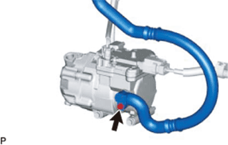
Remove the bolt and disconnect the suction hose sub-assembly from the compressor with motor assembly.
Remove the O-ring from the suction hose sub-assembly.
| 35. REMOVE COMPRESSOR WITH MOTOR ASSEMBLY |
![]() |
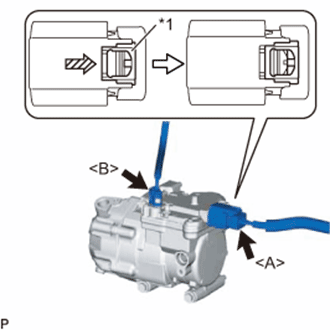
Using a screwdriver, slide the green-colored lock of the connector <A> in the direction indicated by the arrow in the illustration to release it and disconnect the connector.
| *1 | Green-colored Lock |
Disconnect the connector <B>.
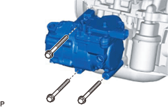
![]() |
Remove the 3 bolts and the compressor with motor assembly.
| 36. REMOVE FRONT EXHAUST PIPE ASSEMBLY |
![]() |
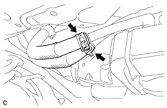
Disconnect the 2 heater water hoses.
![]() |
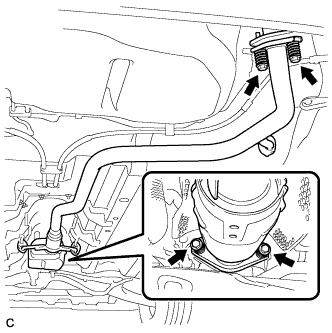
Remove the 4 bolts and 4 compression springs.
Remove the front exhaust pipe assembly from the 3 exhaust pipe supports.
Remove the 2 gaskets from the front exhaust pipe assembly and exhaust manifold.
| 37. SEPARATE NO. 2 ENGINE ROOM RELAY BLOCK AND NO. 2 JUNCTION BLOCK ASSEMBLY |
![]() |
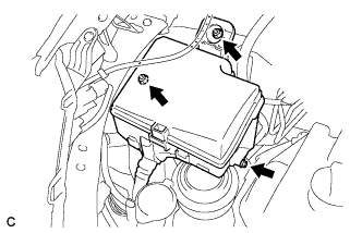
Remove the bolt and 2 nuts, and separate the No. 2 engine room relay block and No. 2 junction block assembly.
| 38. REMOVE FRONT DRIVE SHAFT ASSEMBLY |
| 39. REMOVE FLYWHEEL HOUSING UNDER COVER |
![]() |
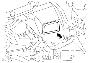
Remove the flywheel housing under cover.
| 40. REMOVE ENGINE ASSEMBLY WITH TRANSAXLE |
![]() |
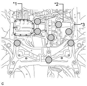
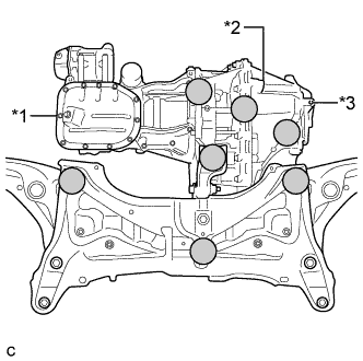
Set the engine lifter.
| *1 | No. 2 Oil Pan Sub-assembly |
| *2 | Drain Plug |
| *3 | Rear Cover Plug |
![]() | Attachment Installation Position |
![]() |
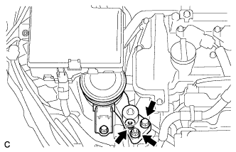
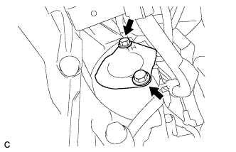
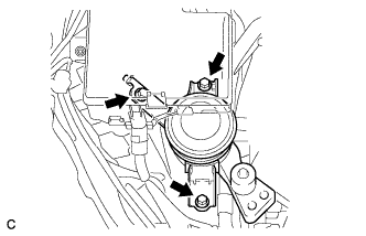
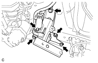
Remove the bolt and 2 nuts, and separate the engine mounting insulator sub-assembly RH from the engine assembly.
![]() |
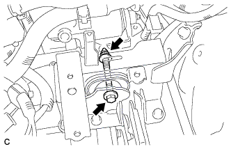
Remove the bolt and nut, and separate the engine mounting insulator LH from the engine mounting bracket LH.
![]() |
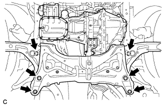
Remove the 6 bolts, operate the engine lifter and slowly remove the engine assembly with transaxle and front suspension crossmember sub-assembly from the vehicle.
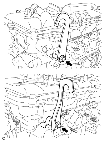
| 41. INSTALL NO. 1 ENGINE HANGER |
![]() |
Install the 2 No. 1 engine hangers with 2 new bolts.
| Part Name | Part No. |
| No. 1 engine hanger | 12281-21090 |
| Bolt | 91672-81025 |
| 42. FIX ENGINE ASSEMBLY WITH TRANSAXLE |
Attach the sling device to the engine hangers and chain block.
![]() |
To enable removal of the engine assembly, adjust the positions of the height adjustment attachment and plate lift attachment and set them in place.
| *1 | No. 2 Oil Pan Sub-assembly |
| *2 | Drain Plug |
| *3 | Rear Cover Plug |
![]() | Attachment Installation Position |
![]() |
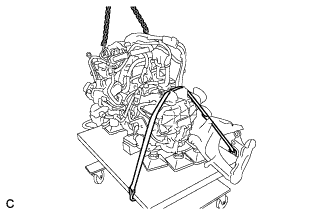
Using a rope or belt, secure the engine assembly with transaxle to the engine lifter.
| 43. REMOVE ENGINE ASSEMBLY |
![]() |
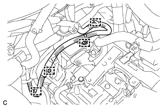
Disconnect the 4 clamps and No. 2 engine wire.
![]() |
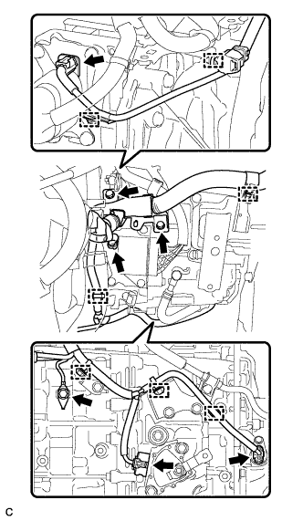
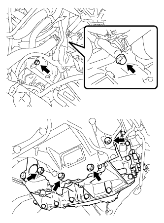
Remove the 3 bolts and disconnect the 4 connectors, 7 clamps and wire harness from the hybrid vehicle transaxle assembly.
![]() |
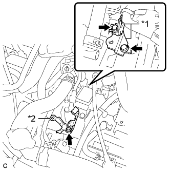
Remove the 3 bolts, 2 wire harness clamp brackets and transmission control cable clamp from the hybrid vehicle transaxle assembly.
| *1 | Wire Harness Clamp Bracket |
| *2 | Transmission Control Cable Clamp |
![]() |
Remove the bolt, nut and drive shaft heat insulator sub-assembly from the engine and drive shaft heat insulator bracket.
![]() |
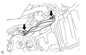
Disconnect the clamp from the drive shaft heat insulator bracket.
Remove the 2 bolts and drive shaft heat insulator bracket from the engine.
![]() |
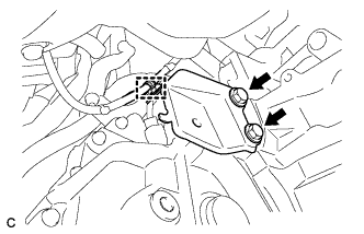
Remove the 2 bolts and starter hole heat insulator from the engine.
![]() |
Disengage the claw and remove the flywheel housing side cover from the engine.
![]() |
Remove the 6 bolts and hybrid vehicle transaxle assembly.
| 44. REMOVE TRANSMISSION INPUT DAMPER ASSEMBLY |
Gently place the engine assembly onto wood blocks or equivalent.
Remove the transmission input damper assembly .
| 45. REMOVE FLYWHEEL SUB-ASSEMBLY |
Gently place the engine assembly onto wooden blocks or equivalent.
Remove the flywheel sub-assembly .
| 46. REMOVE ENGINE MOUNTING INSULATOR SUB-ASSEMBLY RH |
![]() |
Remove the 3 bolts and engine mounting insulator sub-assembly RH.
| 47. REMOVE ENGINE MOUNTING INSULATOR LH |
![]() |
Disconnect the wire harness clamp.
Remove the 5 bolts and engine mounting insulator LH.
| 48. INSTALL ENGINE STAND |
Using a sling device and chain block, install the engine stand to the engine assembly.
| 49. DISCONNECT ENGINE WIRE |
Disconnect all of the clamps and connectors and remove the engine wire from the engine assembly.
| 50. REMOVE NO. 1 ENGINE HANGER |
Remove the 2 bolts and 2 No. 1 engine hangers.