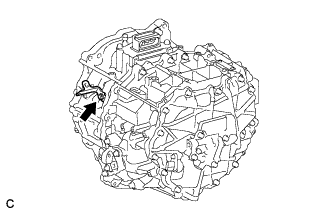
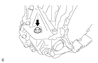
Home › Drivetrain › P510 HYBRID TRANSMISSION / TRANSAXLE › HYBRID VEHICLE TRANSAXLE

HYBRID VEHICLE TRANSAXLE > REMOVAL

for Preparation Click here


1. REMOVE SERVICE PLUG GRIP
(Click here)


2. PLACE FRONT WHEELS FACING STRAIGHT AHEAD


3. REMOVE FRONT WHEELS


4. REMOVE ENGINE UNDER COVER LH


5. REMOVE ENGINE UNDER COVER RH


6. DRAIN COOLANT (for Engine)

NOTICE:
Do not remove the water filler cap sub-assembly, engine drain cock plug or radiator drain cock plug while the engine and radiator are still hot. Pressurized, hot engine coolant and steam may be released and cause serious burns.

  1. Loosen the radiator drain cock plug.


  1. Remove the water filler cap sub-assembly and drain the coolant.
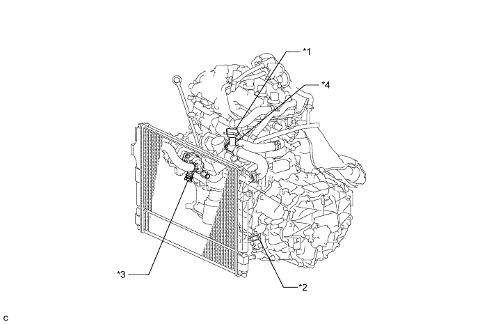

    A267952E01


    Text in Illustration 
    *1
    Water Filler Cap Sub-assembly
    *2
    Radiator Drain Cock Plug
    *3
    Engine Drain Cock Plug
    *4
    Water Filler

    HINT:
    Collect the coolant in a container and dispose of it according to the regulations in your area.
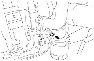


    A267960
  1. Remove the stop ring.


    A268695E01
  1. Connect the hose to the engine drain cock plug.
    Text in Illustration 
    *1
    Hose

  1. Pull out the engine drain cock plug and drain the coolant.


7. DRAIN COOLANT (for Inverter)

NOTICE:
  1. Do not reuse the drained coolant because it may contain foreign matter.
  2. Collect the drained coolant and measure its volume to establish a benchmark. When adding coolant, make sure to add more coolant than the measured amount.

  1. Remove the reserve tank cap.

    CAUTION:
    To avoid the danger of being burned, do not remove the reserve tank cap while the coolant for the inverter is still hot.


    A266681
  1. Loosen the radiator drain cock plug and drain the coolant.

    CAUTION:
    Use caution when handling coolant immediately after driving or in summer because it may be hot.

  1. Tighten the radiator drain cock plug.


8. DRAIN HYBRID TRANSAXLE FLUID


    C249711
  1. Using a 10 mm hexagon socket wrench, remove the filler plug and gasket.


    C249712
  1. Using a 10 mm hexagon socket wrench, remove the drain plug and gasket to drain the hybrid transaxle fluid.

  1. Using a 10 mm hexagon socket wrench, install the drain plug and a new gasket.

    Torque:
    50 N*m{ 510 kgf*cm , 37 ft.*lbf }


9. REMOVE HOOD SUB-ASSEMBLY


    C249809
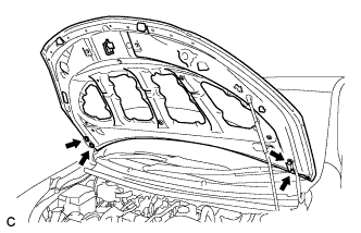
  1. Remove the 4 bolts and hood sub-assembly from the hood hinge assembly LH and hood hinge assembly RH.


10. REMOVE WINDSHIELD WIPER MOTOR AND LINK ASSEMBLY
(Click here)


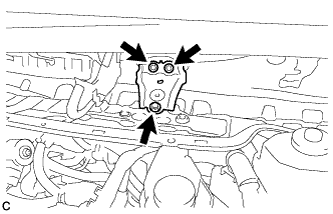
11. REMOVE INNER COWL TOP TO COWL BRACE


    C250011
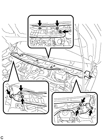
  1. Remove the 3 bolts and inner cowl top to cowl brace.


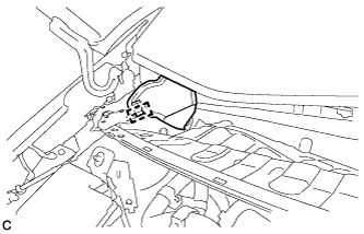
12. REMOVE FRONT AIR SHUTTER SEAL


    C250012
  1. Disengage the clamp to remove the front air shutter seal.


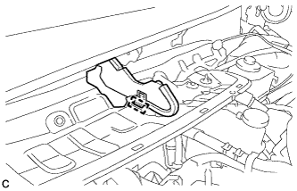
13. REMOVE FRONT NO. 1 VENTILATOR SEAL


    C250013
  1. Disengage the clamp to remove the front No. 1 ventilator seal.


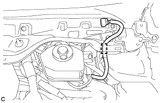
14. REMOVE OUTER COWL TOP PANEL SUB-ASSEMBLY


    C250014
  1. Disengage the clamp to separate the wire harness from the outer cowl top panel sub-assembly.


    C250015
  1. Remove the 8 bolts, nut and outer cowl top panel sub-assembly.


15. REMOVE INVERTER WITH CONVERTER ASSEMBLY
(Click here)


16. REMOVE INVERTER BRACKET ASSEMBLY

CAUTION:
Wear insulated gloves.


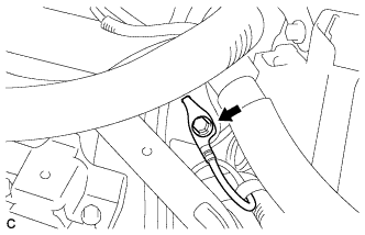
    A268005
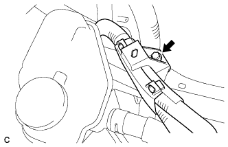
  1. Remove the bolt and separate the motor cable protector.


    A268006
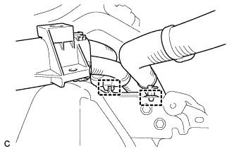
  1. Disconnect the 2 wire harness clamps.


    A268007
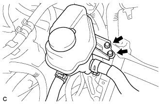
  1. Remove the 2 bolts and separate the inverter reservoir tank assembly.


    A268008
  1. Remove the bolt and disconnect the earth wire.


    A268009
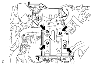
  1. Remove the 4 bolts and inverter bracket assembly.


17. DISCONNECT TRANSMISSION CONTROL CABLE ASSEMBLY


    C249710E01
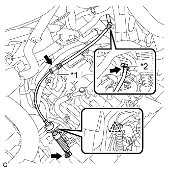
  1. Remove the nut, clip and disconnect the transmission control cable assembly from the No. 1 transmission control cable bracket and transmission control shaft lever.
    Text in Illustration 
    *1
    Transmission Control Cable Clamp
    *2
    Transmission Control Cable Support

  1. Disconnect the transmission control cable assembly from the transmission control cable clamp and transmission control cable support.


18. DISCONNECT WIRE HARNESS


    C249812
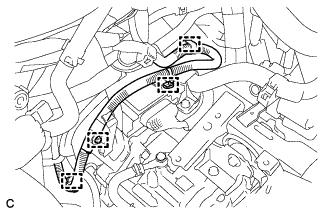
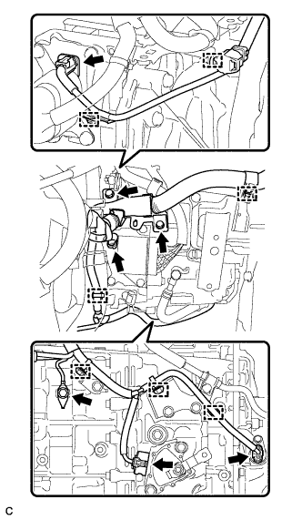
  1. Disconnect the 4 clamps and No. 2 engine wire.


    C249808
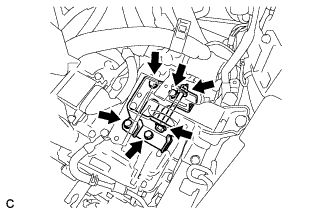
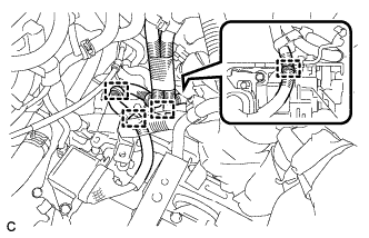
  1. Remove the 3 bolts and disconnect the 4 connectors, 7 clamps and wire harness from the hybrid vehicle transaxle assembly.


19. SECURE STEERING WHEEL


    C247537
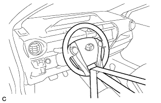
  1. Secure the steering wheel with the seat belt in order to prevent rotation.

    HINT:
    This operation is useful to prevent damage to the spiral cable.


20. REMOVE COLUMN HOLE COVER SILENCER SHEET


    C248046
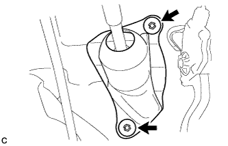
  1. Remove the 2 clips and the column hole cover silencer sheet.


21. SEPARATE STEERING SLIDING YOKE SUB-ASSEMBLY


    C249572E01
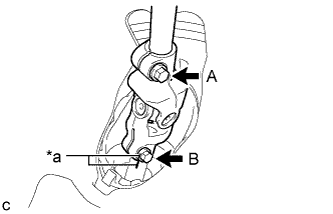
  1. Put matchmarks on the steering sliding yoke sub-assembly and steering gear assembly.
    Text in Illustration 
    *a
    Matchmark

  1. Loosen bolt A.

  1. Remove bolt B.

  1. Separate the steering sliding yoke sub-assembly from the steering gear assembly.


22. SEPARATE NO. 1 STEERING COLUMN HOLE COVER SUB-ASSEMBLY


    C251686E01
  1. Remove clip A, detach clip B from the body and disconnect the No. 1 steering column hole cover sub-assembly.

    NOTICE:
    Do not damage clip B.


23. REMOVE FRONT EXHAUST PIPE ASSEMBLY

CAUTION:
Perform this procedure when the coolant is not hot.


    A267691
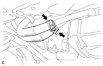
  1. Disconnect the 2 heater water hoses.


    A267690
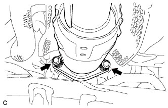
  1. Remove the 2 bolts and 2 compression springs.

  1. Remove the front exhaust pipe assembly from the 3 exhaust pipe supports.

  1. Remove the gasket from the exhaust manifold.


24. REMOVE FRONT DRIVE SHAFT ASSEMBLY
(Click here)


25. REMOVE NO. 2 EGR PIPE


    A268229
  1. Disconnect the wire harness clamp.

  1. Disengage the clamp and disconnect the No. 2 water by-pass hose.

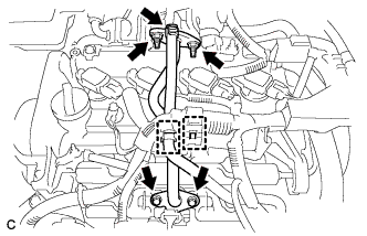
  1. Remove the 2 bolts and 2 nuts.

  1. Remove the No. 2 EGR pipe and 2 gaskets.


26. REMOVE EGR VALVE ASSEMBLY


    A267673
  1. Disconnect the 2 connectors and wire harness clamp.


    A267672
  1. Remove the bolt and wire harness clamp bracket.


    A266465
  1. Disengage the clamp and disconnect the No. 5 water by-pass hose.

  1. Remove the 2 bolts, nut and EGR valve bracket.


    A266466
  1. Disconnect the No. 1 water by-pass hose.


    A267671
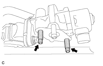
  1. Using an E8 "TORX" socket wrench, remove the 2 stud bolts.


    A266463
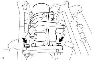
  1. Remove the 2 bolts, EGR valve assembly and gasket.


27. INSTALL NO. 1 ENGINE HANGER


    A214905
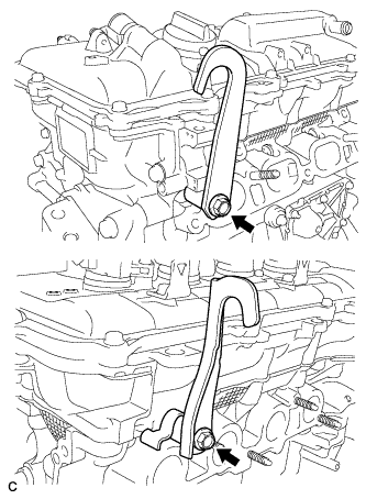
  1. Install the 2 No. 1 engine hangers with 2 new bolts.

    Torque:
    44 N*m{ 448 kgf*cm , 32 ft.*lbf }

    Part Name
    Part No.
    No. 1 engine hanger
    12281-21090
    Bolt
    91672-81025


28. SUSPEND ENGINE ASSEMBLY
  1. Attach the sling device to the engine hangers and chain block.


29. REMOVE FRONT SUSPENSION CROSSMEMBER SUB-ASSEMBLY


    C249868E01
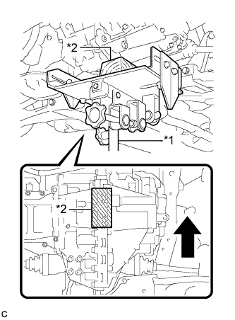
  1. Using a jack and a wooden block, support the engine and transaxle assembly.
    Text in Illustration 
    *1
    Jack
    *2
    Wooden Block
    V100135
    Front of the Vehicle


    C249869
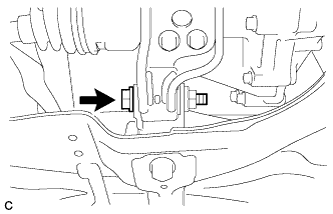
  1. Remove the bolt and separate the engine moving control rod.


    C249867E01
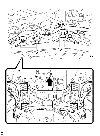
  1. Support the front suspension crossmember sub-assembly with an engine lifter using 4 attachments or equivalent tools as shown in the illustration.
    Text in Illustration 
    *1
    Engine Lifter
    *2
    Attachment
    V100135
    Front of the Vehicle
    V100155
    Attachment Placement Location

    NOTICE:
    1. Make sure to secure the front suspension crossmember sub-assembly to prevent it from dropping.
    2. Use the attachments to keep the front suspension crossmember sub-assembly level.
    3. The front suspension crossmember sub-assembly is a heavy component. Make sure that it is supported securely.


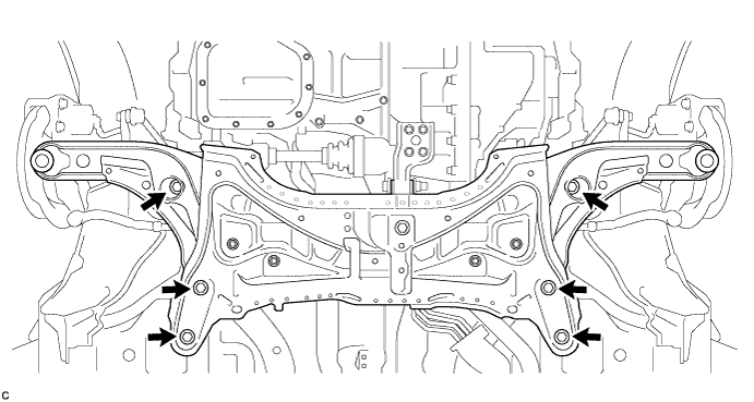
  1. Remove the 6 bolts and front suspension crossmember sub-assembly.


    C249876

  1. Slowly lower the front suspension crossmember sub-assembly.

    NOTICE:
    When lowering the front suspension crossmember sub-assembly, be careful not to damage the vehicle body or other components installed on the vehicle.


30. REMOVE ENGINE LATERAL CONTROL ROD


    C256842
  1. Remove the 4 bolts and engine lateral control rod from the hybrid vehicle transaxle assembly.


31. SUPPORT HYBRID VEHICLE TRANSAXLE ASSEMBLY
  1. Support the hybrid vehicle transaxle assembly with a transmission jack.


32. REMOVE ENGINE MOUNTING BRACKET LH


    C251087
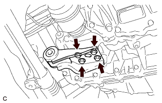
  1. Remove the through bolt, nut and disconnect the engine mounting insulator LH from the engine mounting bracket LH.

  1. Remove the 4 bolts and engine mounting bracket LH from the hybrid vehicle transaxle assembly.


33. REMOVE HYBRID VEHICLE TRANSAXLE ASSEMBLY


    C249795E01
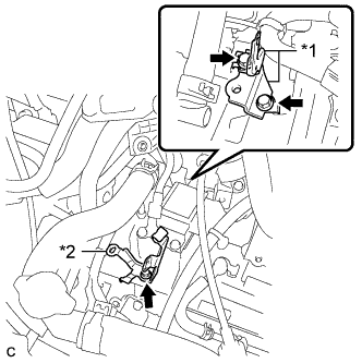
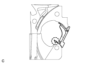
  1. Remove the 3 bolts, 2 wire harness clamp brackets and transmission control cable clamp from the hybrid vehicle transaxle assembly.
    Text in Illustration 
    *1
    Wire Harness Clamp Bracket
    *2
    Transmission Control Cable Clamp


    C249797
  1. Remove the bolt, nut and drive shaft heat insulator sub-assembly from the engine and drive shaft heat insulator bracket.


    C249798
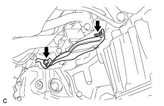
  1. Disconnect the clamp from the drive shaft heat insulator bracket.

  1. Remove the 2 bolts and drive shaft heat insulator bracket from the engine.


    C249799
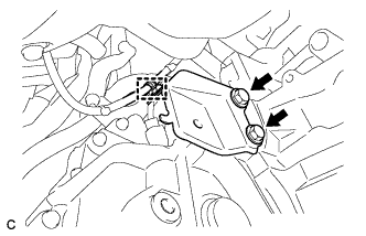
  1. Remove the 2 bolts and starter hole heat insulator from the engine.


    C251104
  1. Disengage the claw and remove the flywheel housing side cover from the engine.


    C250720
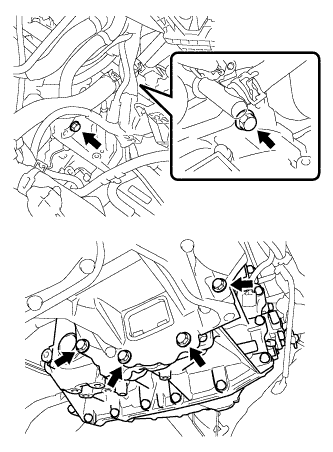
  1. Remove the 6 bolts and hybrid vehicle transaxle assembly.

    NOTICE:
    1. To avoid damage to the knock pins, do not pry between the hybrid vehicle transaxle assembly and the engine.
    2. To prevent the splines of the damper from becoming misaligned, do not allow the transaxle to hit the damper during transaxle removal and installation.


34. REMOVE MOTOR COOLING PIPE ASSEMBLY


    C249801
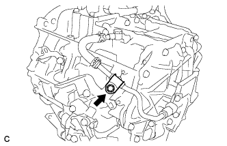
  1. Remove the bolt and oil cooler tube clamp from the No. 1 transmission control cable bracket.


    C249802E01
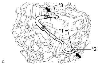
  1. Using a union nut wrench, disconnect the motor cooling pipe assembly from the union.
    Text in Illustration 
    *1
    Flare Nut
    *2
    Union
    *3
    Union Bolt

    HINT:
    Turn the flare nut while holding the union.

  1. Remove the union bolt, gasket and motor cooling pipe assembly from the hybrid vehicle transaxle assembly.


    C249804
  1. Remove the union and O-ring from the hybrid vehicle transaxle assembly.


35. REMOVE MOTOR CABLE

CAUTION:
Wear insulated gloves.


    C249719
  1. Disconnect the 4 clamps and motor cable from the hybrid vehicle transaxle assembly.


  1. Remove the motor cable (for MG 2).


      C249720
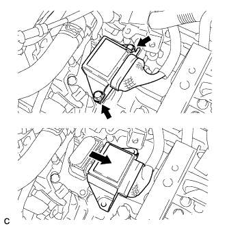
    1. Remove the 2 bolts and slide the connector shell back.


    2. C249721
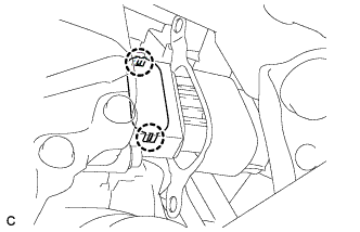
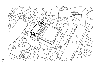
    3. Disengage the 2 claws to remove the terminal cap from the hybrid vehicle transaxle assembly.


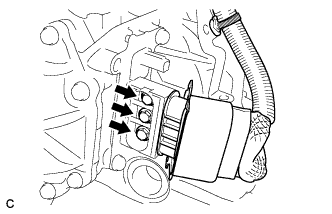
    4. C249722
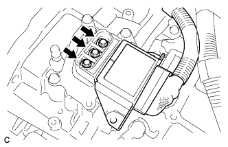
    5. Disconnect the 3 bolts and motor cable from the hybrid vehicle transaxle assembly.


  1. Remove the motor cable (for MG 1).


      C249723
    1. Remove the 2 bolts and slide the connector shell back.


    2. C249724
    3. Disengage the 2 claws to remove the terminal cap from the hybrid vehicle transaxle assembly.


    4. C249725
    5. Remove the 3 bolts and motor cable from the hybrid vehicle transaxle assembly.


36. REMOVE NO. 1 TRANSMISSION CONTROL CABLE BRACKET


    C249805
  1. Remove the 2 bolts and No. 1 transmission control cable bracket from the hybrid vehicle transaxle assembly.


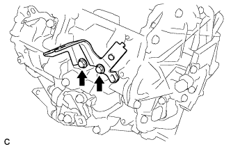
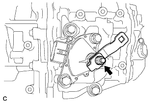
37. REMOVE TRANSMISSION CONTROL SHAFT LEVER


    C250069
  1. Remove the nut, washer, and transmission control shaft lever from the manual valve shaft.


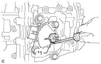
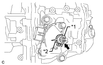
38. REMOVE SHIFT LEVER POSITION SENSOR

HINT:
Perform this procedure only when replacement of the automatic transmission case cover is necessary.


    C250070E01
  1. Using a screwdriver, pry the tabs of the lock plate.
    Text in Illustration 
    *1
    Lock Plate


    C250071E01
  1. Remove the lock nut and lock plate from the manual valve shaft.
    Text in Illustration 
    *1
    Lock Nut
    *2
    Lock Plate


    C250072
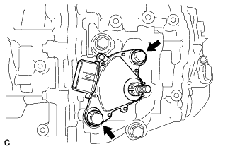
  1. Remove the 2 bolts and pull out the shift lever position sensor from the manual valve shaft.


39. REMOVE AUTOMATIC TRANSMISSION CASE COVER

HINT:
Perform this procedure only when replacement of the automatic transmission case cover is necessary.


    C249807
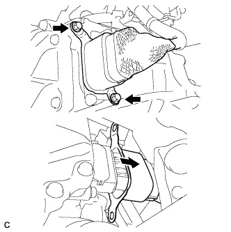
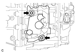
  1. Remove the 2 bolts and automatic transmission case cover from the hybrid vehicle transaxle assembly.


40. REMOVE MOTOR CABLE BRACKET


    C251000
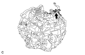
  1. Remove the bolt and motor cable bracket from the transmission control cable support.


41. REMOVE TRANSMISSION CONTROL CABLE SUPPORT


    C251001
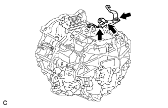
  1. Remove the 3 bolts and 2 transmission control cable supports from the hybrid vehicle transaxle assembly.


42. REMOVE WIRE HARNESS CLAMP BRACKET


    C251002
  1. Remove the bolt and wire harness clamp bracket from the hybrid vehicle transaxle assembly.


43. REMOVE TRANSAXLE HSG AND CASE WITH HEAD STRAIGHT SCREW PLUG


    C249810
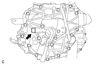
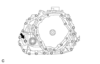
  1. Remove the transaxle HSG and case with head straight screw plug and gasket from the hybrid vehicle transaxle assembly.