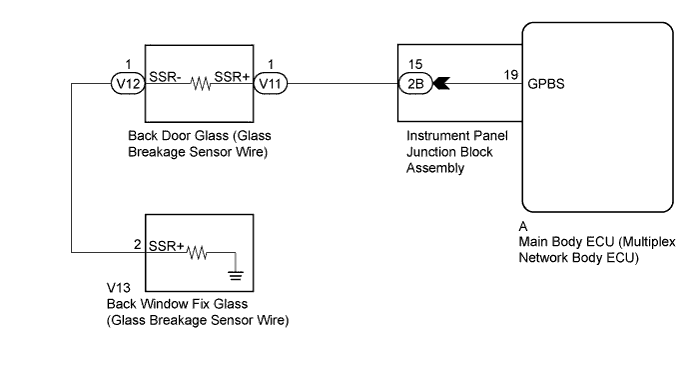
THEFT DETERRENT SYSTEM > Glass Breakage Sensor Circuit |
| 1.CHECK VEHICLE CONDITION (BACK DOOR GLASS AND BACK WINDOW FIX GLASS) |
Check the vehicle condition (back door glass and back window fix glass).
| Result | Proceed to |
| Back door glass is broken or back door glass and back window fix glass are broken. | A |
| Back window fix glass is broken. | B |
|
| ||||
| A | |
 |
| 2.INSPECT INSTRUMENT PANEL JUNCTION BLOCK ASSEMBLY |
Disconnect the A main body ECU (multiplex network body ECU) and 2B instrument panel junction block assembly connectors.
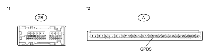
Measure the resistance according to the value(s) in the table below.
| Tester Connection | Condition | Specified Condition |
| A-19 (GPBS) - 2B-15 | Always | Below 1 Ω |
| *1 | Component without harness connected (Instrument Panel Junction Block Assembly) | *2 | Front view of wire harness connector (to Main Body ECU (Multiplex Network Body ECU)) |
|
| ||||
| OK | |
|
| 3.CHECK HARNESS AND CONNECTOR (INSTRUMENT PANEL JUNCTION BLOCK - BACK DOOR GLASS) |
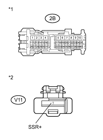 |
Disconnect the V11 back door glass (glass breakage sensor wire) connector.
Measure the resistance according to the value(s) in the table below.
| Tester Connection | Condition | Specified Condition |
| 2B-15 - V11-1 (SSR+) | Always | Below 1 Ω |
| V11-1 (SSR+) - Body ground | Always | 10 kΩ or higher |
| *1 | Front view of wire harness connector (to Instrument Panel Junction Block Assembly) |
| *2 | Front view of wire harness connector (to Back Door Glass (Glass Breakage Sensor Wire)) |
|
| ||||
| OK | ||
 | ||
| ||
| 4.INSPECT INSTRUMENT PANEL JUNCTION BLOCK ASSEMBLY |
Disconnect the A main body ECU (multiplex network body ECU) and 2B instrument panel junction block assembly connectors.
Measure the resistance according to the value(s) in the table below.
| Tester Connection | Condition | Specified Condition |
| A-19 (GPBS) - 2B-15 | Always | Below 1 Ω |
| *1 | Component without harness connected (Instrument Panel Junction Block Assembly) | *2 | Front view of wire harness connector (to Main Body ECU (Multiplex Network Body ECU)) |
|
| ||||
| OK | |
|
| 5.CHECK HARNESS AND CONNECTOR (INSTRUMENT PANEL JUNCTION BLOCK - BACK DOOR GLASS) |
|
Disconnect the V11 back door glass (glass breakage sensor wire) connector.
Measure the resistance according to the value(s) in the table below.
| Tester Connection | Condition | Specified Condition |
| 2B-15 - V11-1 (SSR+) | Always | Below 1 Ω |
| V11-1 (SSR+) - Body ground | Always | 10 kΩ or higher |
| *1 | Front view of wire harness connector (to Instrument Panel Junction Block Assembly) |
| *2 | Front view of wire harness connector (to Back Door Glass (Glass Breakage Sensor Wire)) |
|
| ||||
| OK | |
|
| 6.INSPECT BACK DOOR GLASS (GLASS BREAKAGE SENSOR WIRE) |
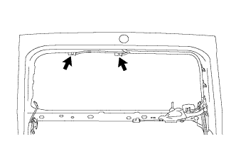 |
Disconnect the V12 back door glass (glass breakage sensor wire) connector.
Measure the resistance according to the value(s) in the table below.
| Tester Connection | Condition | Specified Condition |
| 1 (SSR+) - 1 (SSR-) | Always | Below 1 Ω |
| 1 (SSR+) - 1 (SSR-) | Always | 10 kΩ or higher |
|
| ||||
| OK | |
|
| 7.CHECK HARNESS AND CONNECTOR (BACK DOOR GLASS - BACK WINDOW FIX GLASS) |
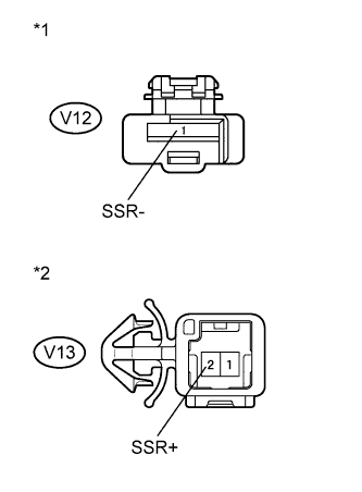 |
Disconnect the V13 back window fix glass (glass breakage sensor wire) connector.
Measure the resistance according to the value(s) in the table below.
| Tester Connection | Condition | Specified Condition |
| V12-1 (SSR-) - V13-2 (SSR+) | Always | Below 1 Ω |
| V12-1 (SSR-) - V13-2 (SSR+) | Always | 10 kΩ or higher |
| *1 | Front view of wire harness connector (to Back Door Glass (Glass Breakage Sensor Wire)) |
| *2 | Front view of wire harness connector (to Back Window Fix Glass (Glass Breakage Sensor Wire)) |
|
| ||||
| OK | ||
| ||
| ||

