Home › Audio / Visual / Telematics › PARK ASSIST / MONITORING › INTELLIGENT PARKING ASSIST SYSTEM

INTELLIGENT PARKING ASSIST SYSTEM > DIAGNOSIS SYSTEM

for Preparation Click here


INTELLIGENT PARKING ASSIST OR DIAGNOSIS SYSTEM
  1. For intelligent parking assist system diagnosis, signals received by the parking assist ECU can be checked and the intelligent parking assist system can be calibrated, adjusted and checked using the navigation receiver assembly.

    NOTICE:
    Depending on the parts that are replaced or operations that are performed during vehicle inspection or maintenance, calibration of other systems as well as the intelligent parking assist system may be needed (Click here).

    HINT:
    The displayed screens and items may differ depending on vehicle specifications.


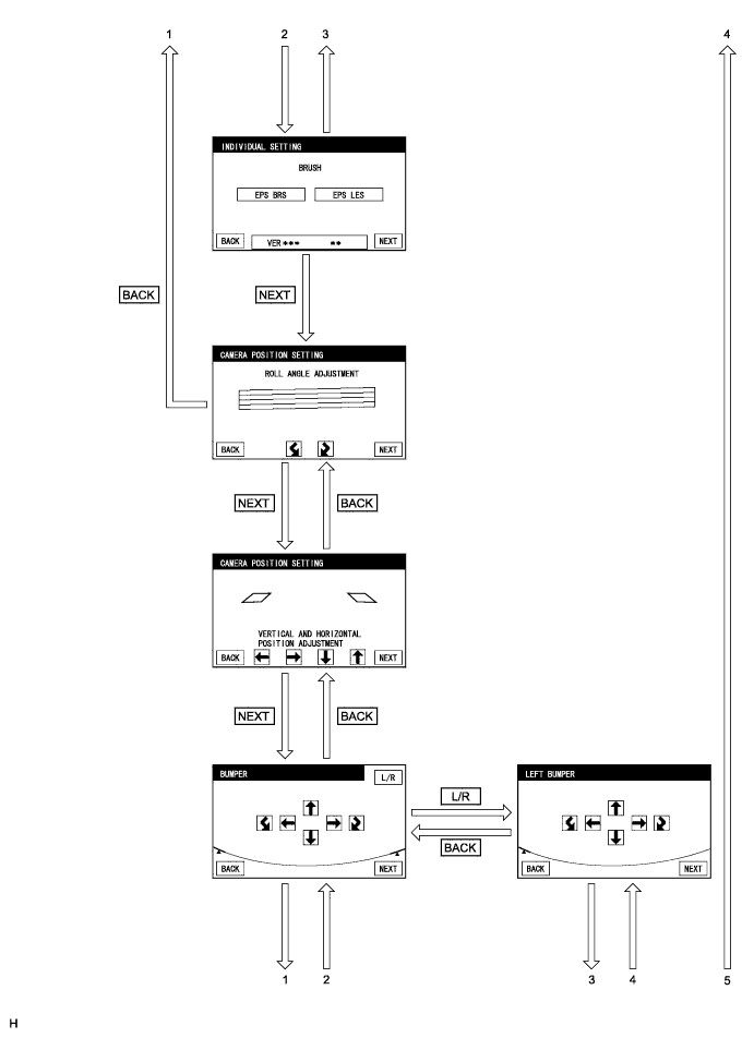
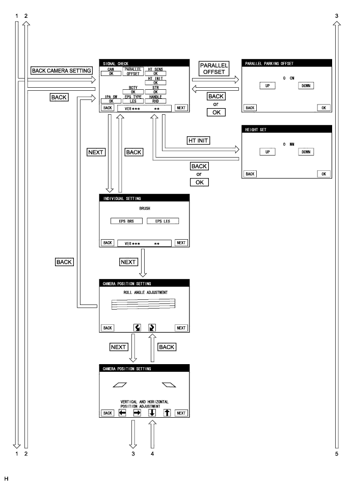
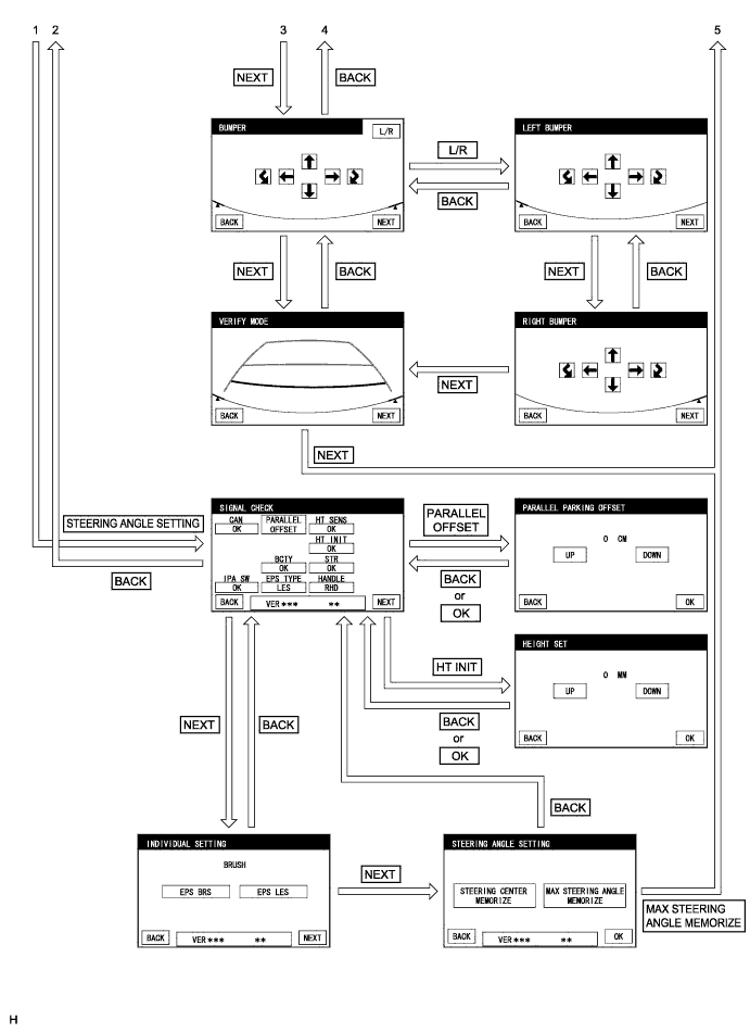
DIAGNOSIS SCREEN TRANSITION (during parking assist ECU initialization)

E188848


E188849


E188850


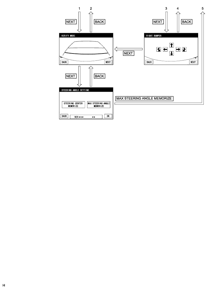
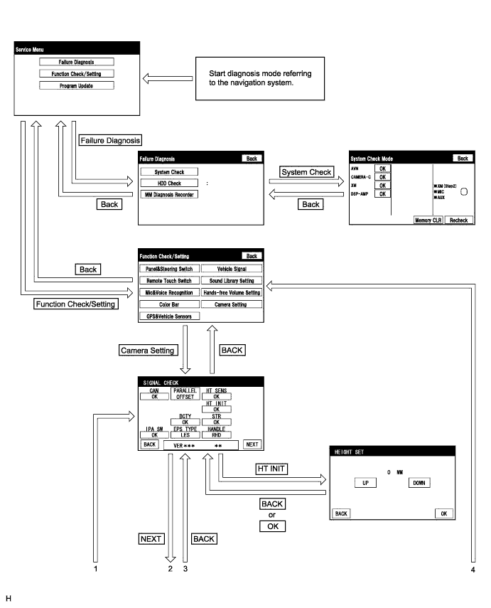
DIAGNOSIS SCREEN TRANSITION (after parking assist ECU initialization)

E188851


E188854


E188855


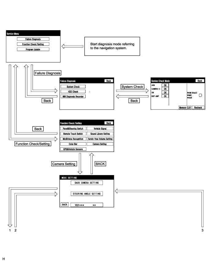
DIAGNOSTIC MODE
  1. Start diagnostic mode (Click here).

  2. Failure diagnosis.

  3. System check (check using system check mode screen).

  4. Finish diagnostic mode.


SIGNAL CHECK (parking assist ECU input signal)


  1. Start diagnostic mode (Click here).


      E180079
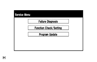
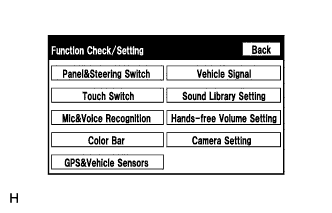
    1. Select "Function Check/Setting" on the Service Menu screen to display the Function Check/Setting screen.


    2. E188885
    3. Select "Camera Setting" on the Function Check/Setting screen.

      HINT:
      After "Camera Setting" is selected, the screen transitions differ depending on whether initialization of the parking assist ECU was performed after parking assist ECU replacement.
      Parking Assist ECU Initialization
      Screen Transition
      Not performed
      SIGNAL CHECK screen
      Performed
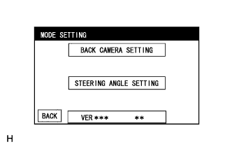
      MODE SETTING screen


    4. E188846
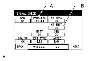
    5. When the screen changes to the MODE SETTING screen, select "BACK CAMERA SETTING" to display the SIGNAL CHECK screen.
      HINT:
      To select a grayed out item, select and hold the item for 2 seconds or more.


  2. E188837E02
  3. SIGNAL CHECK

    1. On the SIGNAL CHECK screen, the following contents are possible:

      1. Inspect the state of signals sent to the parking assist ECU.
      2. Confirm the state of the height control sensor vehicle height difference setting.
      3. Adjust the parking position for parallel parking mode.

      Item
      Inspection Detail
      Note
      CAN
      CAN communication status
      When "CHK" (red) is displayed, selecting "NEXT" will not change to the next screen.
      IPA SW
      Parking assist pre support switch signal input
      BCTY
      CAN communication condition with main body ECU (multiplex network body ECU)
      EPS TYPE
      Brush information for EPS currently selected
      -
      HT SENS
      Height control sensor signal input
      When "CHK" (red) is displayed, selecting "NEXT" will not change to the next screen.
      HT INIT
      Vehicle height difference setting status
      STR
      Steering angle sensor signal input
      HANDLE
      Steering position signal input

      HINT:
      1. When "CHK" (red) is displayed, perform inspections based on the result of the following inspections.
      2. If performing the adjustment after proceeding to the next screen, confirm that all items display "OK" (blue) before selecting "NEXT".
      3. Select the following buttons changes to each adjustment screen.

        Button
        Transit Screen
        Adjustment Contents
        A
        PARALLEL PARKING OFF SET
        Parking position for parallel parking mode
        B
        HEIGHT SET
        Height control sensor vehicle height difference setting (Click here)

  4. CAN inspection

    HINT:
    If "CHK" (red) is displayed for "CAN", check for DTCs and perform troubleshooting based on the output DTCs (Click here).

  5. IPA SW inspection

    1. Check that "OK" (blue) is displayed for "IPA SW" and select "OK".

    2. Check that "OK" (blue) changes to "CHK" (red). Press the parking assist pre support switch and check that "CHK" (red) returns to "OK" (blue).

      HINT:
      If "CHK" (red) remains displayed or the "IPA SW" inspection result is not normal, perform troubleshooting according to Problem Symptoms Table ("CHK" message(s) are displayed on the SIGNAL CHECK screen) (Click here).

  6. BCTY inspection

    HINT:
    If "CHK" (red) is displayed for "BCTY", check for DTCs and perform troubleshooting based on the output DTCs (Click here).

  7. EPS TYPE inspection

    1. Confirm the "EPS LES" is selected on the INDIVIDUAL SETTING screen.

      NOTICE:
      1. If the EPS brush information shown under "EPS TYPE" does not match the vehicle specification, change the EPS brush specification to one that matches the vehicle specification.
      2. The EPS brush specification can be changed on the INDIVIDUAL SETTING screen which is displayed after "NEXT" is selected.
      3. When the EPS brush specification is modified, steering angle setting is required (Click here).

  8. HT SENS inspection

    HINT:
    If "CHK" (red) is displayed for "HT SENS", check for DTCs and perform troubleshooting based on the output DTCs (Click here).

  9. HT INIT inspection

    HINT:
    If "CHK" (red) is displayed for "HT INIT", perform troubleshooting according to the table below.

    Displayed Content
    Cause
    Troubleshooting
    CHK
    (red)
    1. Vehicle height difference setting is not completed
    2. Rear height control sensor sub-assembly RH is malfunctioning
    1. If "CHK" (red) is also displayed for "HT SENS", check for DTCs and perform troubleshooting based on the output DTCs (Click here).
    2. If "OK" (blue) is displayed for "HT SENS", perform vehicle height difference setting (Click here).

  10. STR inspection

    HINT:
    If "CHK" (red) is displayed for "STR", check for DTCs and perform troubleshooting based on the output DTCs (Click here).

  11. HANDLE inspection

    HINT:
    If "CHK" (red) is displayed for "HANDLE", check for DTCs and perform troubleshooting based on the output DTCs (Click here).

  12. Finish diagnostic mode (Click here).


CALIBRATION WHEN SERVICING VEHICLE

NOTICE:
Depending on the parts that are replaced or operations that are performed during vehicle inspection or maintenance, calibration of other systems as well as the intelligent parking assist system may be needed (Click here).


STEERING ANGLE SETTING (after parking assist ECU is initialized)

HINT:
If the vehicle width extension lines and predicted path lines are not aligned when the steering wheel is centered, or if the predicted path line does not move before the steering wheel is fully turned to either the left or right, adjust the steering angle settings.

  1. Center the steering wheel and stop the vehicle.


  2. Start diagnostic mode.

    NOTICE:
    Steering angle setting must be carried out with the hybrid system started. Apply the parking brake, depress the brake pedal, push the P position switch, and ensure that the vehicle is not moving.


      E180079
    1. Select "Function Check/Setting" on the Service Menu screen.


    2. E188885
    3. Select "Camera Setting" on the Function Check/Setting screen.


    4. E188846
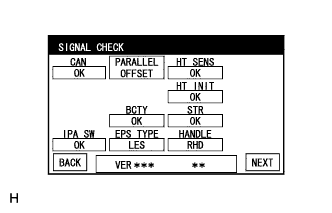
    5. Select "STEERING ANGLE SETTING" on the MODE SETTING screen.
      HINT:
      To select a grayed out item, select and hold the item for 2 seconds or more.


    6. E188837
    7. Select "NEXT" on the SIGNAL CHECK screen.
      NOTICE:
      1. When "CHK" (red) is displayed for any items on the SIGNAL CHECK screen, selecting "NEXT" will not change the screen to the STEERING ANGLE SETTING screen.
      2. When "CHK" is displayed for any items on the SIGNAL CHECK screen, perform inspections using the SIGNAL CHECK screen.


  3. E188839
  4. Individual setting

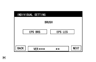
    1. Select the "EPS LES" on the INDIVIDUAL SETTING screen.

      HINT:
      1. Selected EPS brush specification is indicated in blue.
      2. EPS brush refers to the type of motor used for the EPS system (with brushes or brushless).

      NOTICE:
      If the selected EPS brush specification does not match the vehicle specification, select the one that matches the vehicle specification.

    2. Select "NEXT" on the INDIVIDUAL SETTING screen.
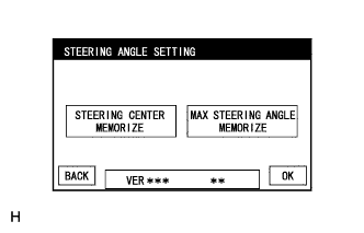
      HINT:
      1. The INDIVIDUAL SETTING screen will not be displayed when "BACK" is selected after switching to the STEERING ANGLE SETTING screen.
      2. To display the INDIVIDUAL SETTING screen again, go back to the Function Check/Setting screen, select "Camera Setting" and repeat the steps.


  5. E180084
  6. Steering angle setting

    1. Check that the steering wheel is centered (approximately +/- 5 degrees or less) and select "STEERING CENTER MEMORIZE".

    2. After the centered steering position is memorized, turn the steering wheel to the left and then to the right full lock positions and select "MAX STEERING ANGLE MEMORIZE".

      HINT:
      It is also possible to start by initially turning the steering wheel to the right side.

    3. Select "MAX STEERING ANGLE MEMORIZE" to store the steering angle adjustment value and change the screen to the MODE SETTING screen.

      HINT:
      1. When "MAX STEERING ANGLE MEMORIZE" is selected, a beep will sound to confirm that the steering angle adjustment values have been stored.
      2. The adjustment values will not be stored unless "MAX STEERING ANGLE MEMORIZE" is selected.
      3. Until a beep finishes sounding, the adjustment values are not stored.
      4. When "BACK" is selected, the screen changes to SIGNAL CHECK without storing the set values.
      5. Even if "OK" is selected, the adjustment values will not be stored.
      6. If the steering angle settings have not been adjusted, selecting "MAX STEERING ANGLE MEMORIZE" will not cause the adjustment values to be stored.
      7. Even if no DTCs are detected, selecting "MAX STEERING ANGLE MEMORIZE" may not cause the adjustment value to be stored if the steering sensor is malfunctioning.
      8. If selecting "MAX STEERING ANGLE MEMORIZE" does not cause the adjustment value to be stored after adjusting the steering angle, replace the spiral with sensor cable sub-assembly (Click here).

  7. Finish diagnostic mode.

  8. Confirm steering angle adjustment.

    HINT:
    If the steering angle has been adjusted, confirm the steering angle adjustment on the intelligent parking assist screen after finishing diagnosis mode.


    1. Check on the intelligent parking assist screen that the predicted path line moves until the steering wheel is fully turned to either the left or right.

      HINT:
      If the predicted path line stops moving before the steering wheel is fully turned to either the left or right, the steering angle adjustment values have not been stored correctly. In this case, perform "STEERING CENTER MEMORIZE" and "MAX STEERING ANGLE MEMORIZE" again.


PARKING POSITION HORIZONTAL ADJUSTMENT FOR PARALLEL PARKING MODE


  1. Start diagnostic mode.

    NOTICE:
    Parallel parking offset must be carried out with the hybrid system started. Apply the parking brake, depress the brake pedal, push the P position switch, and ensure that the vehicle is not moving.


      E180079
    1. Select "Function Check/Setting" on the Service Menu screen.
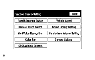


    2. E180081
    3. Select "Camera Setting" on the Function Check/Setting screen.


    4. E188846
    5. Select "BACK CAMERA SETTING" or "STEERING ANGLE SETTING" on the MODE SETTING screen.

      HINT:
      To select a grayed out item, select and hold the item for 2 seconds or more.


    6. E188837
    7. Select "PARALLEL OFFSET" on the SIGNAL CHECK screen.
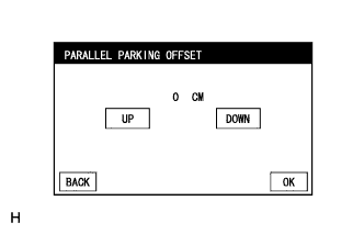


  2. E188847
  3. PARALLEL PARKING OFFSET

    HINT:
    The PARALLEL PARKING OFFSET screen allows the parking position to be offset when the actual parking position deviates to the right or left of the set target parking position during parallel parking mode.


    1. Press "UP" or "DOWN" to adjust the parallel parking position horizontal offset amount.
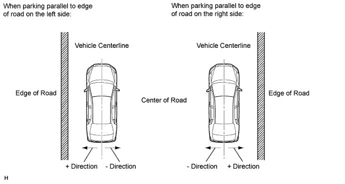

      E193120E01

      HINT:
      1. A positive value is indicated in green and a negative value is indicated in red.
      2. The + direction indicates an offset toward the edge of the road, the - direction indicates an offset toward the road surface.
      3. When a value is shown as "10 CM" in red, it means -10 cm (the parking position is offset 10 cm towards the center of the road).
      4. Available setting range: +20 cm to -40 cm (can be adjusted in 1 cm increments)

    2. When "OK" is selected, the screen switches to the signal connection screen and a set value is stored.

      1. When "OK" is selected, the set value is stored after a "beep" sounds for confirmation.
      2. The memory is not updated until "OK" is selected.
      3. Until a beep finishes sounding, the adjustment values are not stored.
      4. When "BACK" is selected, the screen switches to the signal connection screen without storing a value (values entered are not stored).

  4. Finish diagnostic mode.