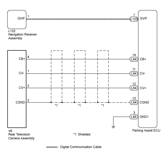
INTELLIGENT PARKING ASSIST SYSTEM > Image from Camera for Intelligent Parking Assist is Abnormal |
| 1.CHECK HARNESS AND CONNECTOR (PARKING ASSIST ECU - REAR TELEVISION CAMERA) |
Disconnect the L64 connector from the parking assist ECU.
Disconnect the V6 connector from the rear television camera assembly.
Measure the resistance according to the value(s) in the table below.
| Tester Connection | Condition | Specified Condition |
| L64-11 (CV-) - V6-1 (CV-) | Always | Below 1 Ω |
| L64-12 (CV+) - V6-2 (CV+) | Always | Below 1 Ω |
| L64-13 (CGND) - V6-3 (CGND) | Always | Below 1 Ω |
| L64-14 (CB+) - V6-4 (CB+) | Always | Below 1 Ω |
| L64-11 (CV-) - Body ground | Always | 10 kΩ or higher |
| L64-12 (CV+) - Body ground | Always | 10 kΩ or higher |
| L64-13 (CGND) - Body ground | Always | 10 kΩ or higher |
| L64-14 (CB+) - Body ground | Always | 10 kΩ or higher |
|
| ||||
| OK | |
 |
| 2.CHECK PARKING ASSIST ECU (CV-, CGND) |
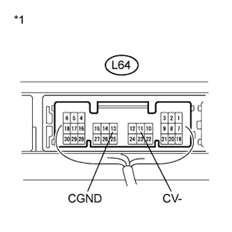 |
Reconnect the L64 connector to the parking assist ECU.
Measure the resistance according to the value(s) in the table below.
| Tester Connection | Condition | Specified Condition |
| L64-11 (CV-) - Body ground | Always | Below 1 Ω |
| L64-13 (CGND) - Body ground | Always | Below 1 Ω |
| *1 | Component with harness connected (Parking Assist ECU) |
|
| ||||
| OK | |
|
| 3.CHECK REAR TELEVISION CAMERA ASSEMBLY (CB+, CGND) |
Disconnect the V6 connector from the rear television camera assembly.
Measure the voltage according to the value(s) in the table below.
| Tester Connection | Condition | Specified Condition |
| V6-3 (CGND) - V6-4 (CB+) | Power switch on (IG) Shift lever in R | 5.8 to 7.0 V |
|
| ||||
| OK | |
|
| 4.CHECK PARKING ASSIST ECU (CV+, GND1) |
Reconnect the V6 connector to the rear television camera assembly.
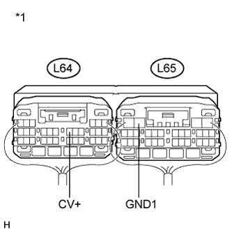 |
Reconnect the L64 and L65 connectors to the parking assist ECU.
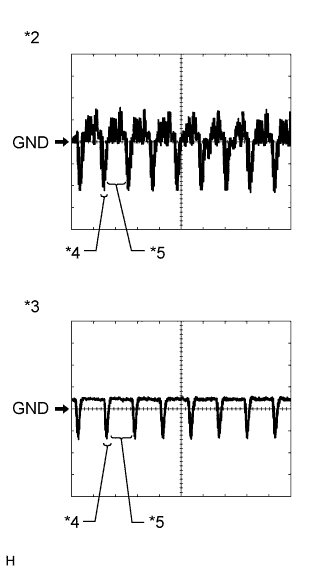 |
Check the waveform of the rear television camera assembly using an oscilloscope.
| Item | Content |
| Terminal No. (Symbol) | L64-12 (CV+) - L65-3 (GND1) |
| Tool Setting | 200 mV/DIV., 50 μsec./DIV. |
| Condition | Power switch on (IG), shift lever in R |
| *1 | Component with harness connected (Parking Assist ECU) |
| *2 | Waveform 1 (under normal conditions) |
| *3 | Waveform 2 (camera lens is covered, blacking out the screen) |
| *4 | Synchronized Signal |
| *5 | Video Waveform |
|
| ||||
| OK | |
|
| 5.READ VALUE USING INTELLIGENT TESTER |
Connect the intelligent tester to the DLC3.
Turn the power switch on (IG).
Turn the intelligent tester on.
Enter the following menus: Chassis / Intelligent Parking Assist / Data List.
Check the Data List for proper functioning of the following items.
| Tester Display | Measurement Item/Range | Normal Condition | Diagnostic Note |
| AISIC Output Status | Output condition of camera display/OK or NG | OK: Output condition of camera display is normal NG: Output condition of camera display is abnormal | - |
|
| ||||
| OK | |
|
| 6.CHECK DIGITAL COMMUNICATION CABLE CONNECTOR |
Check the digital communication cable connectors.
Check the digital communication cable connectors between the parking assist ECU and navigation receiver assembly for any connection problems (Click here).
Check if the same malfunction recurs when the intelligent parking assist screen is displayed.
| Result | Proceed to |
| Malfunction does not reoccur (returns to normal) | A |
| Malfunction reoccurs | B |
|
| ||||
| A | ||
 | ||
| ||
| 7.REPLACE WIRE HARNESS (DIGITAL COMMUNICATION CABLE) |
Replace the digital communication cable between the parking assist ECU and navigation receiver assembly with a new one.
Check if the same malfunction recurs when the intelligent parking assist screen is displayed.
| Result | Proceed to |
| Malfunction does not reoccur (returns to normal) | A |
| Malfunction reoccurs | B |
|
| ||||
| A | ||
| ||
| ||
| 8.REPLACE NAVIGATION RECEIVER ASSEMBLY |
Replace the navigation receiver assembly with a new or normally functioning one (Click here).
Check if the same malfunction recurs when the intelligent parking assist screen is displayed.
| Result | Proceed to |
| Malfunction does not reoccur | A |
| Malfunction reoccurs | B |
|
| ||||
| A | ||
| ||
| ||

