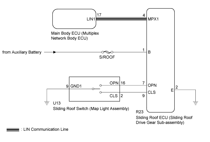
SLIDING ROOF SYSTEM > Sliding Roof does not Move by Operating Sliding Roof Control Switch |
| 1.READ VALUE USING TECHSTREAM |
Connect the Techstream to the DLC3.
Turn the power switch on (IG).
Turn the Techstream on.
Enter the following menus: Body Electrical / Sliding Roof / Data List.
Read the Data List according to the display on the Techstream.
| Tester Display | Measurement Item/Range | Normal Condition | Diagnostic Note |
| Open Switch | OPEN switch signal/ON or OFF | ON: OPEN switch pressed OFF: OPEN switch not pressed | - |
| Close Switch | CLOSE switch signal/ON or OFF | ON: CLOSE switch pressed OFF: CLOSE switch not pressed | - |
|
| ||||
| OK | |
 |
| 2.CHECK HARNESS AND CONNECTOR (SLIDING ROOF ECU - AUXILIARY BATTERY, BODY GROUND) |
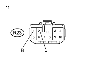 |
Disconnect the sliding roof ECU (sliding roof drive gear sub-assembly) connector.
Measure the voltage according to the value(s) in the table below.
| Tester Connection | Condition | Specified Condition |
| R23-1 (B) - Body ground | Power switch off | 11 to 14 V |
Measure the resistance according to the value(s) in the table below.
| Tester Connection | Condition | Specified Condition |
| R23-2 (E) - Body ground | Always | Below 1 Ω |
| *1 | Front view of wire harness connector (to Sliding Roof ECU (Sliding Roof Drive Gear Sub-assembly)) |
|
| ||||
| OK | ||
 | ||
| ||
| 3.INSPECT SLIDING ROOF SWITCH (MAP LIGHT ASSEMBLY) |
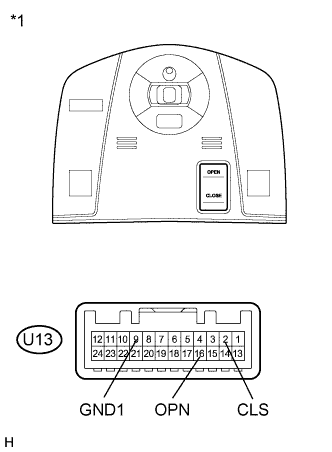 |
Remove the sliding roof switch (map light assembly) (Click here).
Measure the resistance according to the value(s) in the table below.
| Tester Connection | Condition | Specified Condition |
| U13-2 (CLS) - U13-9 (GND1) | CLOSE switch is pressed | Below 1 Ω |
| U13-2 (CLS) - U13-9 (GND1) | CLOSE switch is not pressed | 10 kΩ or higher |
| U13-16 (OPN) - U13-9 (GND1) | OPEN switch is pressed | Below 1 Ω |
| U13-16 (OPN) - U13-9 (GND1) | OPEN switch is not pressed | 10 kΩ or higher |
| *1 | Component without harness connected (Sliding Roof Switch (Map Light Assembly)) |
|
| ||||
| OK | |
|
| 4.CHECK HARNESS AND CONNECTOR (SLIDING ROOF ECU - SLIDING ROOF SWITCH) |
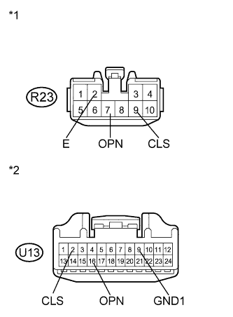 |
Disconnect the sliding roof ECU (sliding roof drive gear sub-assembly) connector.
Measure the resistance according to the value(s) in the table below.
| Tester Connection | Condition | Specified Condition |
| R23-9 (CLS) - U13-2 (CLS) | Always | Below 1 Ω |
| R23-9 (CLS) - Body ground | Always | 10 kΩ or higher |
| R23-7 (OPN) - U13-16 (OPN) | Always | Below 1 Ω |
| R23-7 (OPN) - Body ground | Always | 10 kΩ or higher |
| U13-9 (GND1) - Body ground | Always | Below 1 Ω |
| R23-2 (E) - Body ground | Always | Below 1 Ω |
| *1 | Front view of wire harness connector (to Sliding Roof ECU (Sliding Roof Drive Gear Sub-assembly)) |
| *2 | Front view of wire harness connector (to Sliding Roof Switch (Map Light Assembly)) |
|
| ||||
| OK | ||
| ||
| ||

