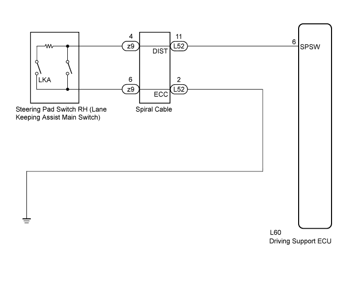
LANE-KEEPING ASSIST SYSTEM > Main Switch Circuit |
| 1.INSPECT STEERING PAD SWITCH RH |
Remove the steering pad switch RH (Click here).
Disconnect the z9 connector from the spiral cable.
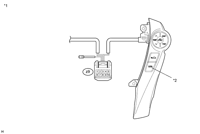
| *1 | Component without harness connected (Steering Pad Switch RH) | *2 | Lane Keeping Assist Main Switch |
Measure the resistance according to the value(s) in the table below.
| Tester Connection | Switch Condition | Specified Condition |
| z9-4 - z9-6 | Lane keeping assist main switch ON | Below 2.5 Ω |
| z9-4 - z9-6 | Lane keeping assist main switch OFF | 10 kΩ or higher |
Reconnect the connector.
Reinstall the steering pad switch RH (Click here).
|
| ||||
| OK | |
 |
| 2.CHECK AND REPLACE SPIRAL CABLE SUB-ASSEMBLY |
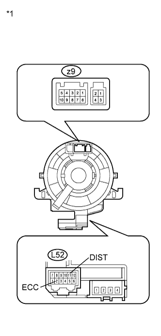 |
Remove the spiral cable sub-assembly (Click here).
Measure the resistance according to the value(s) in the table below.
| Tester Connection | Condition | Specified Condition |
| z9-4 - L52-11 (DIST) | The spiral cable position is center | Below 1 Ω |
| The spiral cable position is 2.5 rotations to the left | ||
| The spiral cable position is 2.5 rotations to the right | ||
| z9-6 - L52-2 (ECC) | The spiral cable position is center | Below 1 Ω |
| The spiral cable position is 2.5 rotations to the left | ||
| The spiral cable position is 2.5 rotations to the right |
| *1 | Component without harness connected (Spiral Cable Sub-assembly) |
Install the spiral cable sub-assembly (Click here).
|
| ||||
| OK | |
|
| 3.CHECK HARNESS AND CONNECTOR (SPIRAL CABLE - DRIVING SUPPORT ECU) |
Disconnect the driving support ECU connector.
Measure the resistance according to the value(s) in the table below.
| Tester Connection | Condition | Specified Condition |
| L52-11 (DIST) - L60-6 (SPSW) | Always | Below 1 Ω |
| L52-11 (DIST) - Body ground | Always | 10 kΩ or higher |
Reconnect the driving support ECU connector.
|
| ||||
| OK | |
|
| 4.CHECK HARNESS AND CONNECTOR (BODY GROUND CIRCUIT) |
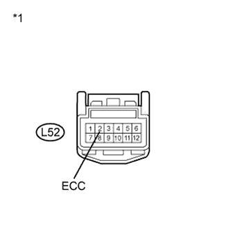 |
Disconnect the spiral cable connector.
Measure the resistance according to the value(s) in the table below.
| Tester Connection | Condition | Specified Condition |
| L52-2 (ECC) - Body ground | Always | Below 1 Ω |
| *1 | Front view of wire harness connector (to Spiral Cable Sub-assembly) |
Reconnect the connector.
|
| ||||
| OK | |
|
| 5.INSPECT DRIVING SUPPORT ECU |
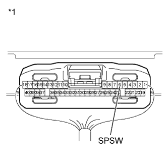 |
Turn the power switch on (IG).
Measure the voltage according to the value(s) in the table below.
| Tester Connection | Switch Condition | Specified Condition |
| L60-6 (SPSW) - Body ground |
| 6 to 7 V |
| 10 to 14 V |
| *1 | Component without harness connected (Driving Support ECU) |
|
| ||||
| OK | ||
 | ||
| ||
