Home › Suspension › TIRE PRESSURE MONITORING › TIRE PRESSURE WARNING SYSTEM

TIRE PRESSURE WARNING SYSTEM > TC and CG Terminal Circuit

for Preparation Click here


DESCRIPTION

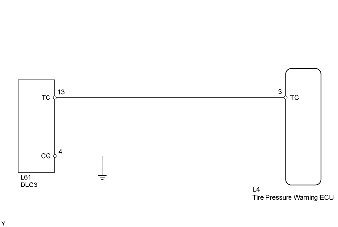
DTC output mode is set by connecting terminals 13 (TC) and 4 (CG) of the DLC3. The DTCs are indicated by the blinking of the tire pressure warning light.

WIRING DIAGRAM


E110507E53

HINT:
When various warning lights blink continuously, a ground short in the wiring of terminal TC of the DLC3 or an internal ground short in an ECU connected to this circuit may have occurred.


INSPECTION PROCEDURE

NOTICE:
  1. When replacing the tire pressure warning ECU, read the transmitter IDs stored in the old ECU using the Techstream and write them down before removal.
  1. It is necessary to perform initialization (Click here) after registration (Click here) of the transmitter IDs into the tire pressure warning ECU after the ECU has been replaced.

1.CHECK HARNESS AND CONNECTOR (DLC3 - TIRE PRESSURE WARNING ECU)
  1. Disconnect the L4 ECU connector.

  1. Measure the resistance according to the value(s) in the table below.

    Standard Resistance:
    Tester Connection
    Condition
    Specified Condition
    L4-3 (TC) - L61-13 (TC)
    Always
    Below 1 Ω
    L61-4 (CG) - Body ground


NG
REPAIR OR REPLACE HARNESS OR CONNECTOR
OK

PROCEED TO NEXT SUSPECTED AREA SHOWN IN PROBLEM SYMPTOMS TABLE (Click here)