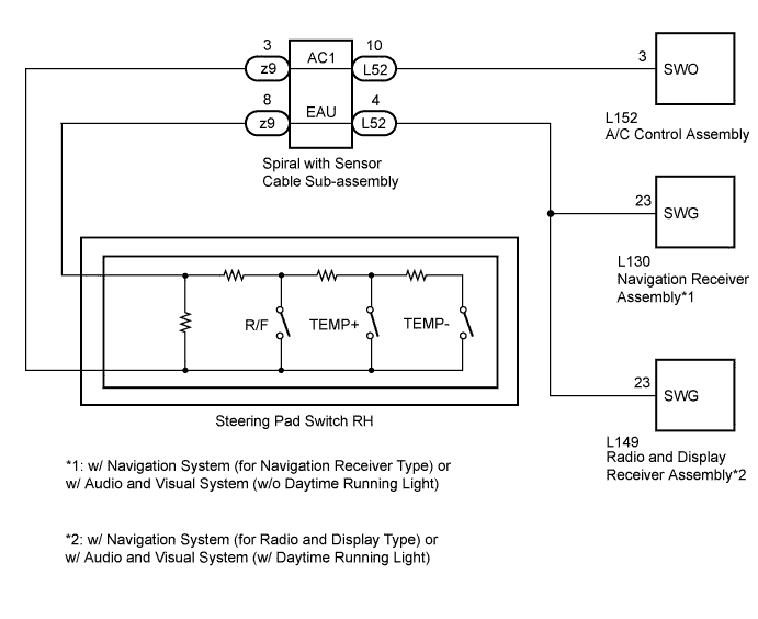
AIR CONDITIONING SYSTEM > Steering Pad Switch Circuit |
| 1.INSPECT A/C CONTROL ASSEMBLY |
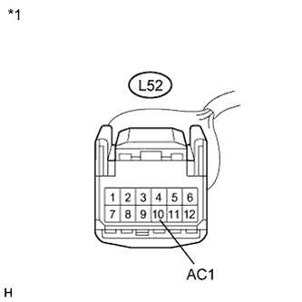 |
Disconnect the connector from the spiral with sensor cable sub-assembly.
Measure the voltage according to the value(s) in the table below.
| Tester Connection | Condition | Specified Condition |
| L52-10 (AC1) - Body ground | Power switch off | Below 1 V |
| L52-10 (AC1) - Body ground | Power switch on (IG) | 4.5 to 5.5 V |
| *1 | Front view of wire harness connector (to Spiral with Sensor Cable Sub-assembly) |
|
| ||||
| OK | |
 |
| 2.CHECK HARNESS AND CONNECTOR |
Disconnect the connector from the navigation receiver assembly*1 or radio and display receiver assembly*2.
Measure the resistance according value(s) in the table below.
| Tester Connection | Condition | Specified Condition |
| L130-23 (SWG) - L52-4 (EAU)*1 | Always | Below 1 Ω |
| L149-23 (SWG) - L52-4 (EAU)*2 | Always | Below 1 Ω |
| L130-23 (SWG) - Body ground*1 | Always | 10 kΩ or higher |
| L149-23 (SWG) - Body ground*2 | Always | 10 kΩ or higher |
|
| ||||
| OK | |
|
| 3.INSPECT STEERING PAD SWITCH RH |
Disconnect the connector from the steering pad switch RH.
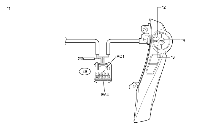
Measure the resistance according to the value(s) in the table below.
| Tester Connection | Condition | Specified Condition |
| z9-3 (AC1) - z9-8 (EAU) | No switch pushed | 95 to 105 kΩ |
| z9-3 (AC1) - z9-8 (EAU) | R/F switch pushed | 323 to 335 Ω |
| z9-3 (AC1) - z9-8 (EAU) | TEMP+ switch pushed | 980 to 1020 Ω |
| z9-3 (AC1) - z9-8 (EAU) | TEMP- switch pushed | 3048 to 3172 Ω |
| *1 | Component without harness connected (Steering Pad Switch RH) | *2 | TEMP+ Switch |
| *3 | TEMP- Switch | *4 | R/F Switch |
|
| ||||
| OK | |
|
| 4.INSPECT SPIRAL WITH SENSOR CABLE SUB-ASSEMBLY |
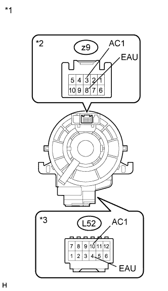 |
Disconnect the connector from the spiral with sensor cable sub-assembly.
Measure the resistance according to the value(s) in the table below.
| Tester Connection | Condition | Specified Condition |
| L52-10 (AC1) - z9-3 (AC1) | Center | Below 1 Ω |
| 2.5 rotations to the left | ||
| 2.5 rotations to the right | ||
| L52-4 (EAU) - z9-8 (EAU) | Center | Below 1 Ω |
| 2.5 rotations to the left | ||
| 2.5 rotations to the right |
| *1 | Component without harness connected (Spiral with Sensor Cable Sub-assembly) |
| *2 | Steering Pad Switch Side |
| *3 | Vehicle Side |
|
| ||||
| OK | |
|
| 5.CONFIRM MODEL |
| Result | Proceed to |
| w/ Navigation System (for Navigation Receiver Type) | A |
| w/ Audio and Visual System (w/o Daytime Running Light) | B |
| w/ Navigation System (for Radio and Display Type) or w/ Audio and Visual System (w/ Daytime Running Light) | C |
|
| ||||
|
| ||||
| A | |
|
| 6.REPLACE NAVIGATION ECU SUB-ASSEMBLY |
Replace the navigation ECU sub-assembly with a known good one and check if the same problem occurs again (Click here).
|
| ||||
| OK | ||
 | ||
| ||
| 7.REPLACE NAVIGATION ECU SUB-ASSEMBLY |
Replace the navigation ECU sub-assembly with a known good one and check if the same problem occurs again (Click here).
|
| ||||
| OK | ||
| ||
| ||
| 8.REPLACE RADIO AND DISPLAY RECEIVER ASSEMBLY |
Replace the radio and display receiver assembly with a known good one and check if the same problem occurs again (Click here).
|
| ||||
| OK | ||
| ||
| ||
| 9.CHECK HARNESS AND CONNECTOR (A/C CONTROL ASSEMBLY - SPIRAL WITH SENSOR CABLE SUB-ASSEMBLY) |
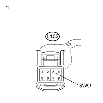 |
Disconnect the connector from the A/C control assembly.
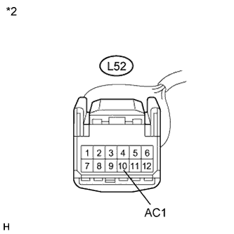 |
Measure the resistance according value(s) in the table below.
| Tester Connection | Condition | Specified Condition |
| L152-3 (SWO) - L52-10 (AC1) | Always | Below 1 Ω |
| L152-3 (SWO) - Body ground | Always | 10 kΩ or higher |
| *1 | Front view of wire harness connector (to A/C Control Assembly) |
| *2 | Front view of wire harness connector (to Spiral with Sensor Cable Sub-assembly) |
|
| ||||
| OK | ||
| ||
| ||

