DTC B2275 STSW Monitor Malfunction |
| DTC No. | DTC Detection Condition | Trouble Area |
| B2275 | Power management control ECU internal HV activation request output circuit malfunction or external circuit malfunction. |
|
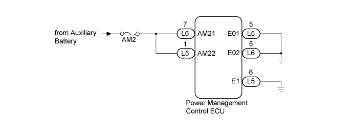
| 1.CHECK HARNESS AND CONNECTOR (AUXILIARY BATTERY - POWER MANAGEMENT CONTROL ECU) |
Disconnect the L5 and L6 connectors from the power management control ECU.
Measure the voltage according to the value(s) in the table below.
| Tester Connection | Condition | Specified Condition |
| L5-1 (AM22) - Body ground | Always | 9.5 to 16 V |
| L6-7 (AM21) - Body ground | Always | 9.5 to 16 V |
|
| ||||
| OK | |
 |
| 2.CHECK HARNESS AND CONNECTOR (POWER MANAGEMENT CONTROL ECU - BODY GROUND) |
Measure the resistance according to the value(s) in the table below.
| Tester Connection | Condition | Specified Condition |
| L5-5 (E01) - Body ground | Always | Below 1 Ω |
| L5-6 (E1) - Body ground | Always | Below 1 Ω |
| L6-4 (E12) - Body ground | Always | Below 1 Ω |
| L6-5 (E02) - Body ground | Always | Below 1 Ω |
|
| ||||
| OK | |
|
| 3.CHECK FOR DTC |
Clear the DTC (Click here).
Turn the power switch on (IG).
After 25 seconds have elapsed, check if the DTC has been set again.
|
| ||||
| OK | ||
 | ||
| ||
