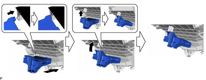
Temporarily install the air conditioning amplifier assembly as shown in the illustration.
AIR CONDITIONING UNIT > INSTALLATION |
| 1. INSTALL NO. 2 AIR DUCT SUB-ASSEMBLY |
Engage the 3 claws to install the No. 2 air duct sub-assembly.
| 2. INSTALL NO. 3 AIR DUCT SUB-ASSEMBLY |
Engage the 3 claws to install the No. 3 air duct sub-assembly.
| 3. INSTALL AIR CONDITIONING HARNESS ASSEMBLY |
Connect each connector.
Engage each clamp to install the air conditioning harness assembly.
| 4. INSTALL AIR CONDITIONING AMPLIFIER ASSEMBLY |
Temporarily install the air conditioning amplifier assembly as shown in the illustration.
Install the air conditioning amplifier assembly with the screw.
Connect the connector.
| 5. INSTALL ASPIRATOR |
Engage the 2 claws and install the aspirator.
| 6. INSTALL AIR CONDITIONING RADIATOR ASSEMBLY |
Install the air conditioning radiator assembly with the 3 screws.
Connect the connector.
| 7. TEMPORARILY TIGHTEN AIR CONDITIONER UNIT ASSEMBLY |
Temporarily tighten the air conditioning unit with the 3 bolts and nut.
| 8. CONNECT DRAIN COOLER HOSE |
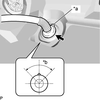 |
Install the drain cooler hose as shown in the illustration.
| *a | UP Mark |
| *b | 90° |
| 9. INSTALL DEFROSTER NOZZLE ASSEMBLY |
Engage the 2 claws and 3 guides to install the defroster nozzle assembly.
| 10. INSTALL INSTRUMENT PANEL REINFORCEMENT ASSEMBLY |
Install the instrument panel reinforcement with the 8 bolts.
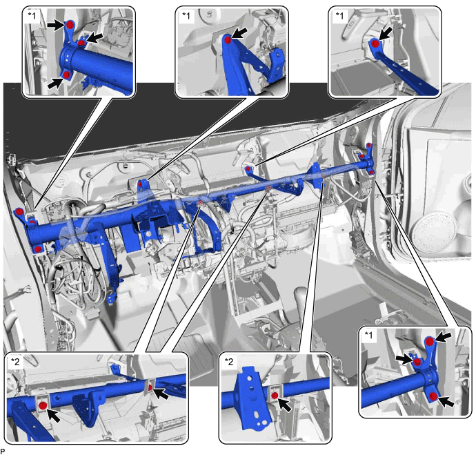
| *1 | Bolt | *2 | Screw |
Temporarily tighten the 3 screws.
| 11. CONNECT INSTRUMENT PANEL WIRE (for LHD) |
Engage each clamp.
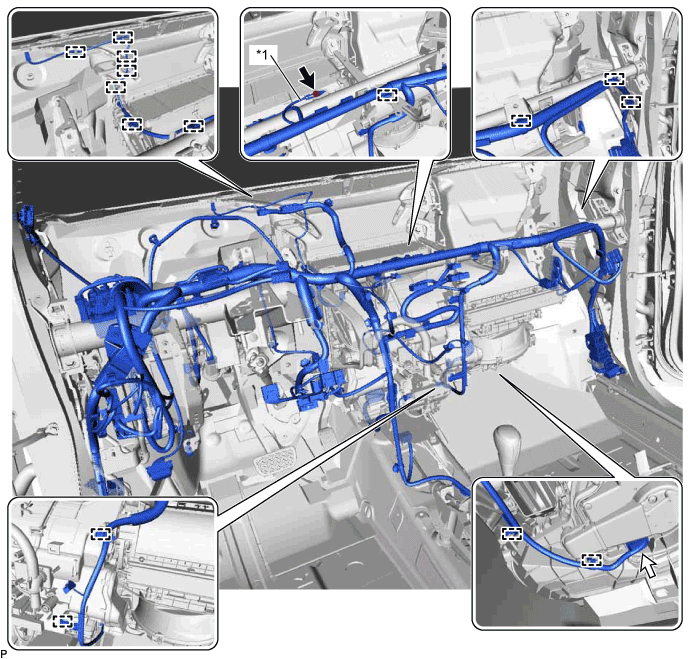
| *1 | Earth Wire | - | - |
Connect the connector.
Install the earth wire with the bolt.
Engage each clamp.
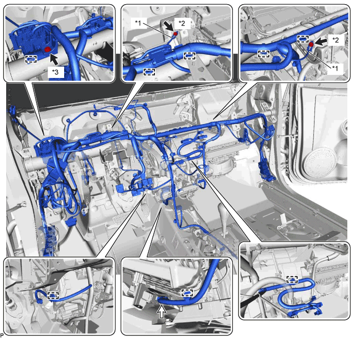
| *1 | Earth Wire | *2 | Bolt <A> |
| *2 | Bolt <B> | - | - |
Connect the connector.
Install the bolt <B>.
Install the 2 earth wires with the 2 bolts <A>.
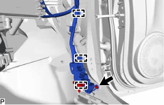 |
for RH Side:
Engage each clamp and connect the connector holder.
Install the bolt.
Connect each connector.
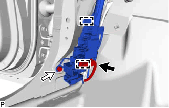 |
for LH Side:
Engage each clamp and connect the connector holder.
Connect the connector to the connector holder.
Install the bolt.
Connect each connector.
| 12. CONNECT INSTRUMENT PANEL WIRE (for RHD) |
Engage each clamp.
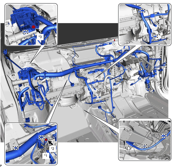
| *1 | Earth Wire | *2 | Bolt <A> |
| *3 | Bolt <B> | - | - |
Connect the connector.
Install the bolt <B>.
Install the earth wire with the bolt <A>.
Engage each clamp.
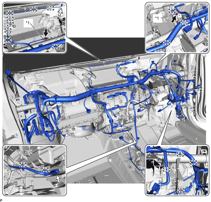
| *1 | Earth Wire | - | - |
Connect each connector.
Install the 2 earth wires with the 2 bolts.
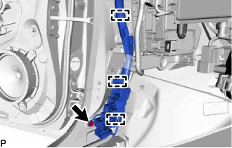 |
for LH Side:
Engage each clamp and connect the connector holder.
Install the bolt.
Connect each connector.
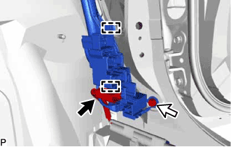 |
for RH Side:
Engage each clamp and connect the connector holder.
Connect the connector to the connector holder.
Install the bolt.
Connect each connector.
| 13. INSTALL NO. 1 INSTRUMENT PANEL BRACE SUB-ASSEMBLY (for LHD) |
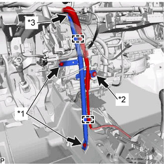 |
Install the No. 1 instrument panel brace sub-assembly with the 2 bolts, screw and nut.
| *1 | Bolt |
| *2 | Screw |
| *3 | Nut |
Engage each clamp.
| 14. INSTALL NO. 1 INSTRUMENT PANEL BRACE SUB-ASSEMBLY (for RHD) |
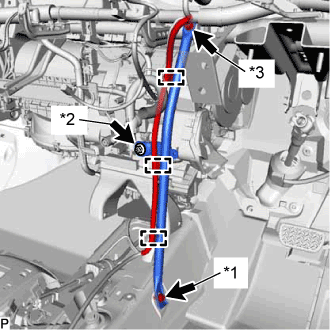 |
Install the No. 1 instrument panel brace sub-assembly with the bolt, screw and nut.
| *1 | Bolt |
| *2 | Screw |
| *3 | Nut |
Engage each clamp.
| 15. INSTALL AIR CONDITIONER UNIT ASSEMBLY |
Tighten install the 2 No. 1 air duct bolts.
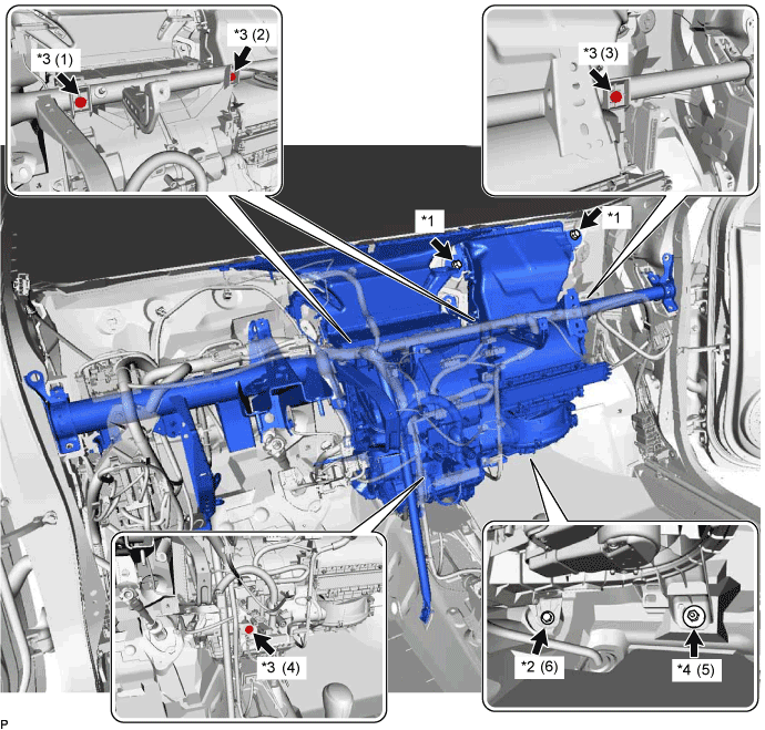
| *1 | No. 1 air duct bolt | *2 | Bolt |
| *3 | Screw | *4 | Nut |
Install the bolt, nut and 4 screws in the order shown in the illustration.
| 16. INSTALL FRONT FLOOR CARPET ASSEMBLY |
Install the front floor carpet assembly.
| 17. INSTALL NO. 2 INDOOR ELECTRICAL KEY ANTENNA ASSEMBLY |
Engage the clamp and Install the No. 2 indoor electrical key antenna assembly.
Connect the connector.
| 18. INSTALL NO. 1 INDOOR ELECTRICAL KEY ANTENNA ASSEMBLY |
Engage the clamp to install the No. 1 indoor electrical key antenna assembly.
Connect the connector.
| 19. INSTALL POWER STEERING ECU ASSEMBLY (for LHD) |
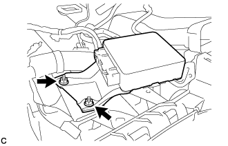 |
Install the power steering ECU assembly with the 2 nuts.
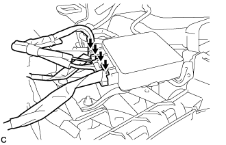 |
Connect the 4 connectors to the power steering ECU assembly.
| 20. INSTALL POWER STEERING ECU ASSEMBLY (for RHD) |
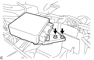 |
Install the power steering ECU assembly with the 2 nuts.
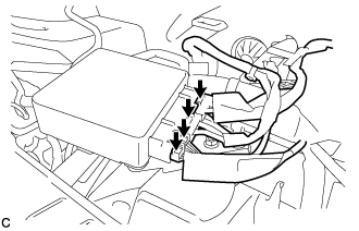 |
Connect the 4 connectors to the power steering ECU assembly.
| 21. INSTALL INSTRUMENT PANEL JUNCTION BLOCK ASSEMBLY (for LHD) |
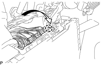 |
Engage the claw to connect the connector as shown in the illustration.
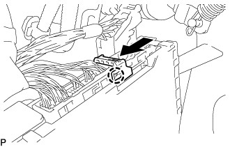 |
Engage the claw to lock the connector lock as shown in the illustration.
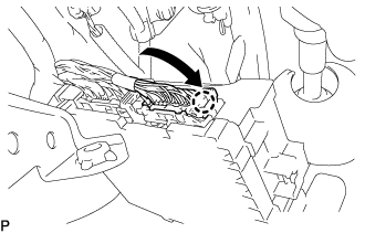 |
Engage the claw to connect the connector as shown in the illustration.
Engage the 2 clamps to connect the wire harness.
Install the instrument panel junction block assembly with the 2 bolts.
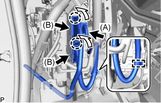 |
Connect the connector (A).
Engage the 2 claws to connect the 2 connectors (B) as shown in the illustration.
Engage the clamp to connect the wire harness.
| 22. INSTALL INSTRUMENT PANEL JUNCTION BLOCK ASSEMBLY (for RHD) |
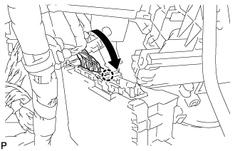 |
Engage the claw to connect the connector as shown in the illustration.
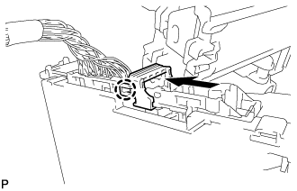 |
Engage the claw to lock the connector lock as shown in the illustration.
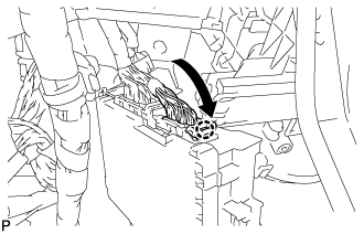 |
Engage the claw to connect the connector as shown in the illustration.
Engage the 2 clamps to connect the wire harness.
Install the instrument panel junction block assembly with the 2 bolts.
for Halogen Headlight:
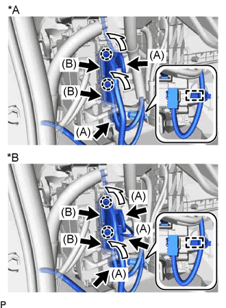 |
Connect the 2 connectors (A).
| *A | for Halogen Headlight: |
| *B | for LED Headlight: |
for LED Headlight:
Connect the 3 connectors (A).
Engage the 2 claws to connect the 2 connectors (B) as shown in the illustration.
Engage the clamp.
| 23. CONNECT INSTRUMENT PANEL WIRE |
Engage the 2 clamps to connect the instrument panel wire.
Install the bolt.
| 24. INSTALL POWER MANAGEMENT CONTROL ECU |
Install the power management control ECU with the 2 nuts.
Connect the 4 connectors.
| 25. INSTALL STEERING COLUMN ASSEMBLY |
| 26. INSTALL LOWER INSTRUMENT PANEL SUB-ASSEMBLY |
| 27. CONNECT WATER HOSE SUB-ASSEMBLY |
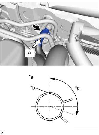 |
Connect the water hose with the marking (white) facing up and engage the clip within the area shown in the illustration.
| *a | View A |
| *b | Water Hose Sub-assembly Marking (White) |
| *c | Clip installation angle (60° to 150°) |
| 28. CONNECT HEATER WATER OUTLET HOSE A |
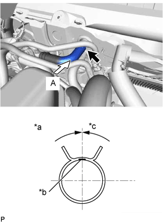 |
Connect heater water outlet hose A with the marking (purple) facing up and engage the clip within the area shown in the illustration.
| *a | View A |
| *b | Heater Water Outlet Hose A Marking (Purple) |
| *c | Clip installation angle (-45° to 45°) |
| 29. CONNECT LIQUID PIPE SUB-ASSEMBLY |
Remove the vinyl tape from the liquid pipe sub-assembly.
Sufficiently apply compressor oil to a new O-ring and fitting surface of the liquid pipe sub-assembly.
Install the O-ring to the liquid pipe sub-assembly.
Install the liquid pipe sub-assembly.
| 30. CONNECT SUCTION PIPE SUB-ASSEMBLY |
Remove the vinyl tape from the suction pipe sub-assembly.
Sufficiently apply compressor oil to a new O-ring and fitting surface of the suction pipe sub-assembly.
Install the O-ring to the suction pipe sub-assembly.
Connect the suction pipe sub-assembly.
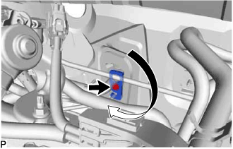 |
Rotate the hook connector in the direction indicated by the arrow in the illustration.
Insert the pipe joint into the fitting hole securely and tighten the bolt.
| 31. INSTALL OUTER COWL TOP PANEL SUB-ASSEMBLY (for LHD) |
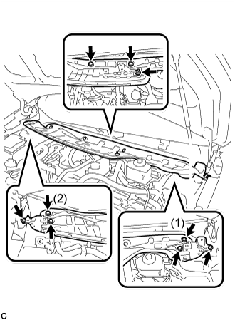 |
Install the outer cowl top panel sub-assembly with the 8 bolts and nut.
Engage the clamp to install the wire harness.
| 32. INSTALL OUTER COWL TOP PANEL SUB-ASSEMBLY (for RHD) |
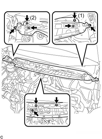 |
Install the outer cowl top panel sub-assembly with the 8 bolts and nut.
Engage the 3 clamps to install the wire harness.
| 33. INSTALL FRONT NO. 1 VENTILATOR SEAL (for LHD) |
Engage the clamp to install the front No. 1 ventilator seal to the outer cowl top panel sub-assembly.
| 34. INSTALL FRONT NO. 1 VENTILATOR SEAL (for RHD) |
Engage the clamp to install the front No. 1 ventilator seal to the outer cowl top panel sub-assembly.
| 35. INSTALL FRONT AIR SHUTTER SEAL (for LHD) |
Engage the clamp to install the front air shutter seal to the outer cowl top panel sub-assembly.
| 36. INSTALL FRONT AIR SHUTTER SEAL (for RHD) |
Engage the clamp to install the front air shutter seal to the outer cowl top panel sub-assembly.
| 37. INSTALL INNER COWL TOP TO COWL BRACE (for LHD) |
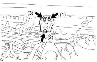 |
Install the inner cowl top to cowl brace to the outer cowl top panel sub-assembly with the 3 bolts.
| 38. INSTALL INNER COWL TOP TO COWL BRACE (for RHD) |
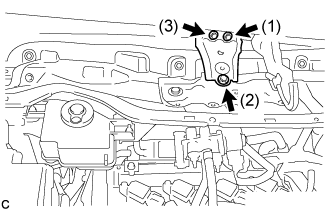 |
Install the inner cowl top to cowl brace to the outer cowl top panel sub-assembly with the 3 bolts.
| 39. INSTALL WINDSHIELD WIPER MOTOR AND LINK |
| 40. INSPECT FOR COOLANT LEAK (for Engine) |
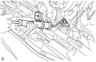 |
Fill the radiator with coolant and attach a radiator cap tester.
Put the engine in inspection mode (Click here).
Warm up the engine.
Using a radiator cap tester, increase the pressure inside the radiator to 108 kPa (1.1 kgf/cm2, 16 psi), and check that the pressure does not drop.
If the pressure drops, check the hoses, radiator, engine water pump, front exhaust pipe assembly and engine coolant temperature sensor for leaks. If no external leaks are found, check the heater core, cylinder block and cylinder head.
| 41. INSPECT ENGINE COOLANT LEVEL IN RESERVOIR (for Engine) |
Check that the engine coolant level is between the low and full lines when the engine is cold.
If the engine coolant level is low, check for leaks and add "TOYOTA Super Long Life Coolant" or similar high quality ethylene glycol based non-silicate, non-amine, non-nitrite and non-borate coolant with long-life hybrid organic acid technology to the full line.
| 42. CHARGE AIR CONDITIONING SYSTEM WITH REFRIGERANT |
Perform vacuum purging using a vacuum pump or appropriate equipment.
Charge the air conditioning system with refrigerant.
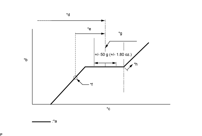
| *a | Sub-cool System | *b | High Pressure |
| *c | Refrigerant Amount | *d | Standard charge amount |
| *e | Charge additional 100g (3.5 oz.) | *f | Point where bubbles disappear |
| *g | Mean value in proper range | *h | Overcharged |
| 43. WARM UP COMPRESSOR |
Keep the A/C switch on for at least 2 minutes to warm up the compressor.
| 44. INSPECT FOR REFRIGERANT LEAK |
After recharging the air conditioning system with refrigerant, inspect for refrigerant leaks using a halogen leak detector.
Carry out the test under the following conditions:
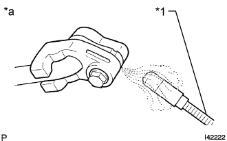 |
Using a halogen leak detector, inspect for refrigerant leaks from the air conditioning system.
| *1 | Halogen Leak Detector |
| *a | Inspect for Leak |
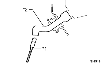 |
Bring the halogen leak detector close to the drain hose with the detector power off, and then turn the detector on.
| *1 | Halogen Leak Detector |
| *2 | Drain Hose |
If a refrigerant leak is not detected from the drain hose, remove the blower motor control from the cooling unit. Insert the halogen leak detector sensor into the unit and check for a leak.
Disconnect the pressure sensor connector and leave it for approximately 20 minutes. Bring the halogen leak detector close to the pressure sensor and check for a leak.