 |
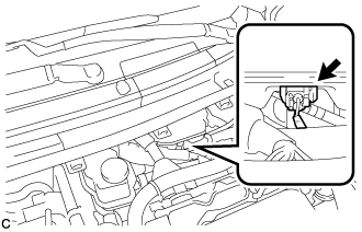
Disconnect the reservoir level switch connector with the parking brake applied.
REAR BRAKE > REMOVAL |
| 1. PRECAUTION |
| 2. DISABLE BRAKE CONTROL |
Wait at least 2 minutes after turning the power switch off.
|
Disconnect the reservoir level switch connector with the parking brake applied.
Disconnect the cable from the negative (-) auxiliary battery terminal (Click here).
Depress the brake pedal 40 times or more to return all the fluid in the accumulator back to the reservoir.
Check that the brake pedal can not be further depressed.
Release the parking brake.
| 3. REMOVE REAR WHEEL |
| 4. DRAIN BRAKE FLUID |
| 5. LOOSEN LOCK NUT |
| 6. REMOVE REAR BRAKE DRUM SUB-ASSEMBLY |
 |
Release the parking brake and remove the rear brake drum.
 | Contract |
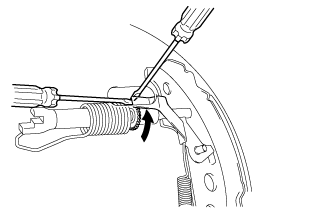
Remove the shoe adjusting hole plug and insert a screwdriver through the hole into the backing plate, and hold the automatic adjust lever away from the adjuster.
Using another screwdriver, contract the brake shoe by turning the adjusting bolt.
| 7. REMOVE REAR BRAKE STRUT KIT |
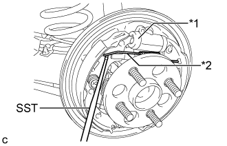 |
Using SST, separate the tension spring from the rear brake shoe.
| *1 | Wheel Cylinder Boot |
| *2 | Tension Spring |
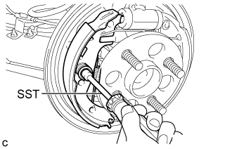 |
Using SST, remove the 2 shoe hold down spring cups, shoe hold down spring, pin and rear brake shoe.
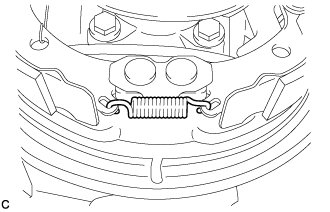 |
Remove the shoe tension spring.
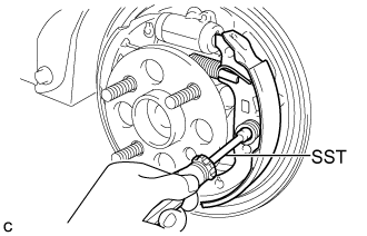 |
Using SST, remove the 2 shoe hold down spring cups, shoe hold down spring, pin and rear brake shoe.
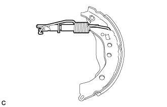 |
Remove the tension spring from the rear brake shoe and remove the rear brake strut kit.
| 8. SEPARATE NO. 3 PARKING BRAKE CABLE ASSEMBLY |
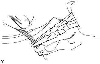 |
Using needle-nose pliers, separate the No. 3 parking brake cable assembly.
| 9. REMOVE REAR BRAKE AUTOMATIC ADJUST LEVER |
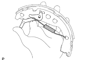 |
Remove the rear brake automatic adjust lever tension spring and rear brake automatic adjust lever.
| 10. REMOVE REAR DRUM BRAKE BLEEDER PLUG CAP |
| 11. REMOVE REAR DRUM BRAKE BLEEDER PLUG |
| 12. REMOVE REAR WHEEL BRAKE CYLINDER ASSEMBLY |
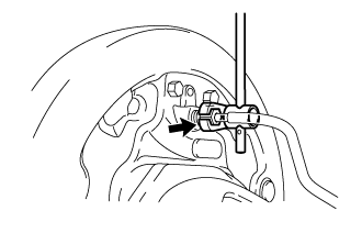 |
Using a union nut wrench, disconnect the brake line from the rear brake wheel cylinder assembly.
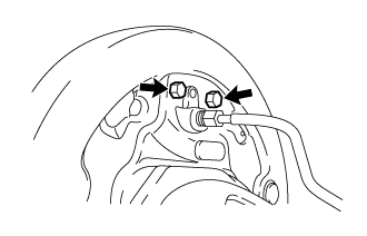 |
Remove the 2 bolts and rear wheel brake cylinder assembly from the backing plate.