 |
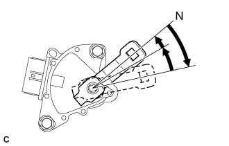
Turn the lever clockwise until it stops, then turn it counterclockwise 2 notches.
HYBRID VEHICLE TRANSAXLE > INSTALLATION |
| 1. INSTALL TRANSAXLE HSG AND CASE WITH HEAD STRAIGHT SCREW PLUG |
Install a new gasket and the transaxle HSG and case with head straight screw plug to the hybrid vehicle transaxle assembly.
| 2. INSTALL WIRE HARNESS CLAMP BRACKET |
Install the wire harness clamp bracket to the hybrid vehicle transaxle assembly with the bolt.
| 3. INSTALL TRANSMISSION CONTROL CABLE SUPPORT |
Install the 2 transmission control cable supports to the hybrid vehicle transaxle assembly with the 3 bolts.
| 4. INSTALL MOTOR CABLE BRACKET |
Install the motor cable bracket to the transmission control cable support with the bolt.
| 5. INSTALL AUTOMATIC TRANSMISSION CASE COVER |
Install the automatic transmission case cover to the hybrid vehicle transaxle assembly with the 2 bolts.
| 6. INSTALL SHIFT LEVER POSITION SENSOR |
Install the shift lever position sensor to the manual valve shaft.
Temporarily install the 2 bolts.
Install a new lock plate and tighten the nut.
Temporarily install the control shaft lever to the manual valve shaft.
|
Turn the lever clockwise until it stops, then turn it counterclockwise 2 notches.
Remove the control shaft lever from the manual valve shaft.
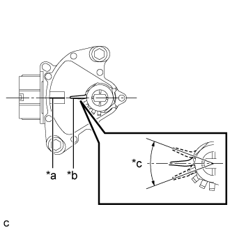 |
Align the protruding part with the neutral basic line.
| *a | Neutral Basic Line |
| *b | Protruding |
| *c | Range of Play |
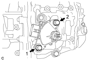 |
Tighten the 2 bolts in the order shown in the illustration.
Using a screwdriver, secure the nut with the lock plate.
| 7. INSTALL TRANSMISSION CONTROL SHAFT LEVER |
Install the transmission control shaft lever, washer, and nut to the manual valve shaft.
| 8. INSTALL NO. 1 TRANSMISSION CONTROL CABLE BRACKET |
Install the No. 1 transmission control cable bracket to the hybrid vehicle transaxle assembly with the 2 bolts.
| 9. INSTALL MOTOR CABLE |
Install the motor cable (for MG 1).
Install the motor cable to the hybrid vehicle transaxle assembly with the 3 bolts.
Engage the 2 claws to install a new terminal cap to the hybrid vehicle transaxle assembly.
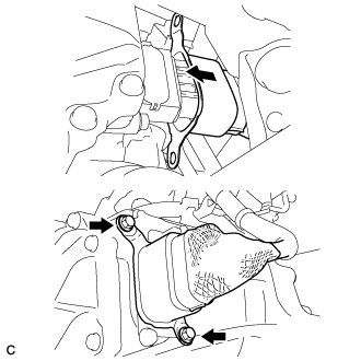 |
Place the connector shell in position and install it with the 2 bolts.
Install the motor cable (for MG 2).
Install the motor cable to the hybrid vehicle transaxle assembly with the 3 bolts.
Engage the 2 claws to install a new terminal cap to the hybrid vehicle transaxle assembly.
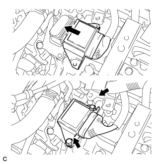 |
Place the connector shell in position and install it with the 2 bolts.
Connect the 4 clamps and install the motor cable to the hybrid vehicle transaxle assembly.
| 10. INSTALL MOTOR COOLING PIPE ASSEMBLY |
Install a new O-ring and union to the hybrid vehicle transaxle assembly.
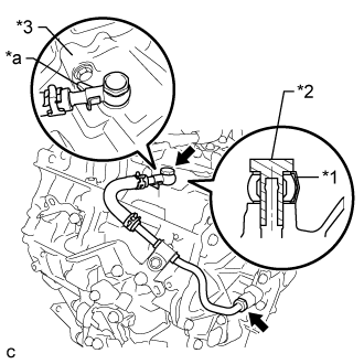 |
Temporarily tighten the motor cooling pipe assembly to the hybrid vehicle transaxle assembly with a new gasket and union bolt.
| *1 | Gasket |
| *2 | Union Bolt |
| *3 | Transaxle Case |
| *a | Stopper |
Install the oil cooler tube clamp and motor cooling pipe assembly to the No. 1 transmission control cable bracket with the bolt.
Tighten the union bolt with the motor cooling pipe assembly stopper pressed against the transaxle case.
Using a union nut wrench, connect the motor cooling pipe assembly to the union.
| 11. INSTALL HYBRID VEHICLE TRANSAXLE ASSEMBLY |
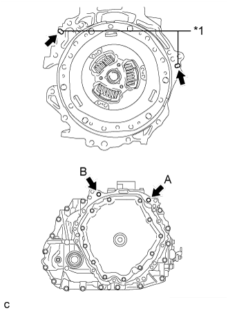 |
Make sure that the knock pins are installed to the engine.
| *1 | Knock Pin |
Temporarily install the hybrid vehicle transaxle assembly to the engine with the 2 bolts.
Fully tighten the 2 bolts in the order of A and B.
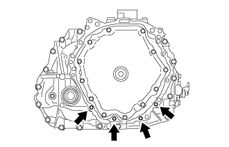 |
Install the 4 bolts.
Engage the claw and install the flywheel housing side cover to the engine.
Install the starter hole heat insulator to the engine with the 2 bolts.
Install the drive shaft heat insulator bracket to the engine with the 2 bolts.
Connect the clamp to the drive shaft heat insulator bracket.
Install the drive shaft heat insulator sub-assembly to the engine and drive shaft heat insulator bracket with the bolt and nut.
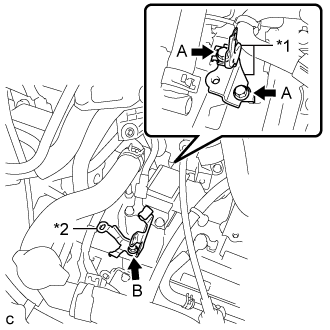 |
Install the 2 wire harness clamp brackets and transmission control cable clamp to the hybrid vehicle transaxle assembly with the 3 bolts.
| *1 | Wire Harness Clamp Bracket |
| *2 | Transmission Control Cable Clamp |
| 12. INSTALL ENGINE MOUNTING BRACKET LH |
Clean and degrease the bolts and bolt holes.
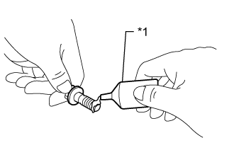 |
Apply adhesive to 4 bolts.
| *1 | Adhesive |
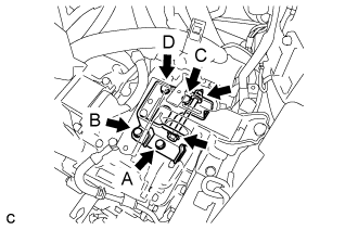 |
Temporarily install the engine mounting bracket LH to the hybrid vehicle transaxle assembly with the 4 bolts.
Fully tighten the 4 bolts in the order of A, B, C and D.
Install the engine mounting insulator LH to the engine mounting bracket LH with the through bolt and nut.
| 13. INSTALL ENGINE LATERAL CONTROL ROD |
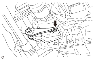 |
Temporarily tighten the engine lateral control rod to the hybrid vehicle transaxle assembly with the bolt.
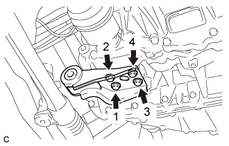 |
Tighten the 4 bolts in the order shown in the illustration.
| 14. INSTALL FRONT SUSPENSION CROSSMEMBER SUB-ASSEMBLY |
Support the front suspension crossmember sub-assembly with an engine lifter using 4 attachments or equivalent tools.
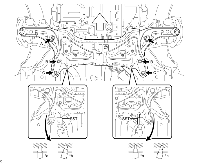
Temporarily tighten the front suspension crossmember sub-assembly to the body with the 6 bolts.
Tighten the 2 bolts A and 2 bolts C on the left and right sides while alternately inserting SST into the left and right side reference holes in the front suspension crossmember sub-assembly.
| *a | OK | *b | NG |
 | Front of the Vehicle | - | - |
Lower the engine lifter.
Install the engine moving control rod with the bolt.
| 15. REMOVE NO. 1 ENGINE HANGER |
Remove the 2 bolts and 2 No. 1 engine hangers.
| 16. INSTALL EGR VALVE ASSEMBLY |
Install a new gasket.
Install the EGR valve assembly with the 2 bolts.
Using an E8 "TORX" socket wrench, install the 2 stud bolts.
Connect the No. 1 water by-pass hose.
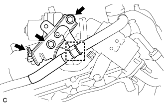 |
Install the EGR valve bracket with the 2 bolts and nut.
Connect the clamp and No. 5 water by-pass hose.
Install the wire harness clamp bracket with the bolt.
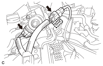 |
Connect the 2 connectors and wire harness clamp.
| 17. INSTALL NO. 2 EGR PIPE |
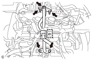 |
Install 2 new gaskets and the No. 2 EGR pipe with the 2 bolts and 2 nuts.
Connect the clamp and No. 2 water by-pass hose.
Connect the wire harness clamp.
| 18. INSTALL FRONT DRIVE SHAFT ASSEMBLY |
| 19. INSTALL FRONT EXHAUST PIPE ASSEMBLY |
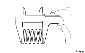 |
Using a vernier caliper, measure the free length of the compression springs.
| Minimum | 41.5 mm (1.64 in.) |
Fully insert a new gasket to the exhaust manifold converter sub-assembly.
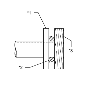 |
Using a plastic hammer and wooden block, tap in the new gasket until its surface is flush with the exhaust manifold.
| *1 | Exhaust Manifold Converter Sub-assembly |
| *2 | Gasket |
| *3 | Wooden Block |
Connect the front exhaust pipe assembly to the 3 exhaust pipe supports.
Install the front exhaust pipe assembly with the 2 bolts and 2 compression springs.
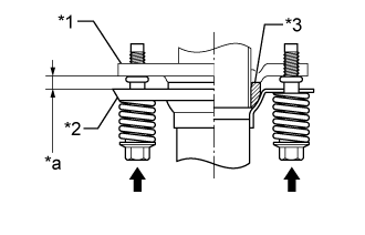 |
| *1 | Exhaust Manifold |
| *2 | Front Exhaust Pipe Assembly |
| *3 | Gasket |
| *a | Space between flanges: 8.5 mm (0.335 in.) |
| 20. INSTALL NO. 1 STEERING COLUMN HOLE COVER SUB-ASSEMBLY |
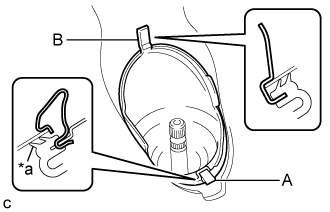 |
Place clip A as shown in the illustration and engage clip B to the body to connect the No. 1 steering column hole cover sub-assembly.
| *a | Lip |
| 21. INSTALL STEERING SLIDING YOKE SUB-ASSEMBLY |
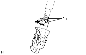 |
Install the steering sliding yoke sub-assembly to the No. 2 steering intermediate shaft assembly.
| *a | Matchmark |
Temporarily install the bolt.
| 22. INSTALL COLUMN HOLE COVER SILENCER SHEET |
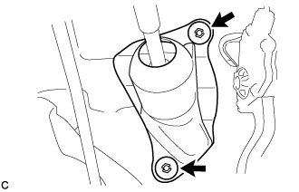 |
Install the column hole cover silencer sheet with the 2 clips.
Install the floor carpet.
| 23. INSTALL WIRE HARNESS |
Connect the 7 clamps, 4 connectors and install the wire harness to the hybrid vehicle transaxle assembly with the 3 bolts.
Connect the 4 clamps and No. 2 engine wire.
| 24. INSTALL TRANSMISSION CONTROL CABLE ASSEMBLY |
Connect the transmission control cable assembly to the transmission control cable clamp and transmission control cable support.
Connect the transmission control cable assembly to the No. 1 transmission control cable bracket with a new clip.
Install the transmission control cable assembly to the transmission control shaft lever with the nut.
| 25. INSTALL INVERTER BRACKET ASSEMBLY |
Temporarily install the inverter bracket assembly with the 4 bolts.
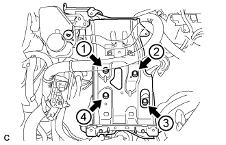 |
Tighten the 4 bolts in the sequence shown in the illustration.
Connect the earth wire with the bolt.
Install the inverter reservoir tank assembly with the 2 bolts.
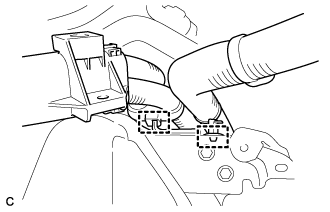 |
Connect the 2 wire harness clamps.
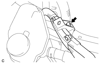 |
Connect the motor cable protector with the bolt.
| 26. INSTALL INVERTER WITH CONVERTER ASSEMBLY |
| 27. INSTALL OUTER COWL TOP PANEL SUB-ASSEMBLY (for LHD) |
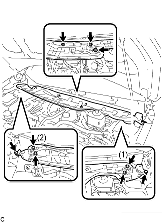 |
Install the outer cowl top panel sub-assembly with the 8 bolts and nut.
Engage the clamp to install the wire harness.
| 28. INSTALL OUTER COWL TOP PANEL SUB-ASSEMBLY (for RHD) |
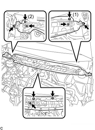 |
Install the outer cowl top panel sub-assembly with the 8 bolts and nut.
Engage the 3 clamps to install the wire harness.
| 29. INSTALL FRONT NO. 1 VENTILATOR SEAL (for LHD) |
Engage the clamp to install the front No. 1 ventilator seal to the outer cowl top panel sub-assembly.
| 30. INSTALL FRONT NO. 1 VENTILATOR SEAL (for RHD) |
Engage the clamp to install the front No. 1 ventilator seal to the outer cowl top panel sub-assembly.
| 31. INSTALL FRONT AIR SHUTTER SEAL (for LHD) |
Engage the clamp to install the front air shutter seal to the outer cowl top panel sub-assembly.
| 32. INSTALL FRONT AIR SHUTTER SEAL (for RHD) |
Engage the clamp to install the front air shutter seal to the outer cowl top panel sub-assembly.
| 33. INSTALL INNER COWL TOP TO COWL BRACE (for LHD) |
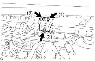 |
Install the inner cowl top to cowl brace to the outer cowl top panel sub-assembly with the 3 bolts.
| 34. INSTALL INNER COWL TOP TO COWL BRACE (for RHD) |
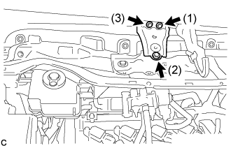 |
Install the inner cowl top to cowl brace to the outer cowl top panel sub-assembly with the 3 bolts.
| 35. INSTALL WINDSHIELD WIPER MOTOR AND LINK ASSEMBLY |
| 36. INSTALL HOOD SUB-ASSEMBLY |
Install the hood sub-assembly to the hood hinge assembly LH and hood hinge assembly RH with the 4 bolts.
| 37. INSPECT HOOD SUB-ASSEMBLY |
Check that the clearance measurements of areas "a" through "f" are within each standard range.
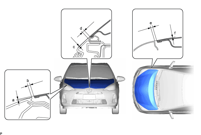
| Area | Measurement | Area | Measurement |
| a | -0.85 to 3.15 mm (-0.0335 to 0.124 in.) | b | 1.65 to 5.65 mm (0.065 to 0.222 in.) |
| c | -1.85 to 2.15 mm (-0.0728 to 0.0847 in.) | d | 2.35 to 6.35 mm (0.0925 to 0.25 in.) |
| e | 2.0 to 5.0 mm (0.0787 to 0.197 in.) | f | -1.5 to 1.5 mm (-0.0591 to 0.0591 in.) |
| 38. ADJUST HOOD SUB-ASSEMBLY |
Horizontally and vertically adjust the hood.
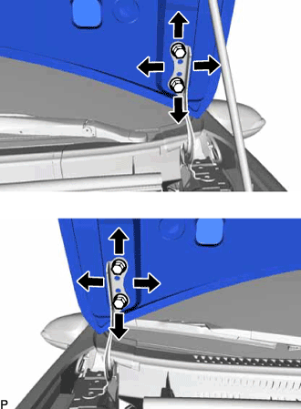 |
Loosen the 4 hinge bolts of the hood.
Adjust the clearance between the hood and front fender by moving the hood.
Tighten the 4 hinge bolts after the adjustment.
Adjust the height of the front end of the hood using the cushion rubbers.
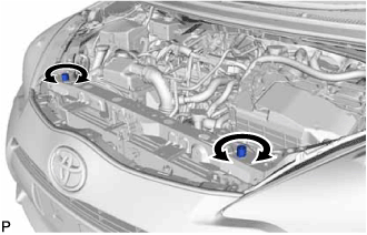 |
Adjust the 2 cushion rubbers so that the heights of the hood and fender are aligned.
Adjust the hood lock.
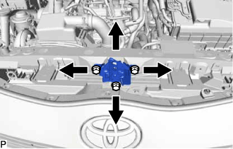 |
Loosen the 3 bolts.
Tighten the bolts after adjustment.
Check that the striker can engage with the hood lock smoothly.
| 39. INSTALL SERVICE PLUG GRIP |
| 40. ADD COOLANT (for Engine) |
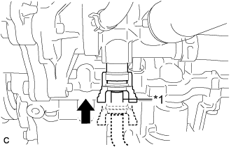 |
Insert the engine drain cock plug.
| *1 | Hose |
Disconnect the hose from the engine drain cock plug.
Install the stop ring.
Tighten the radiator drain cock plug by hand.
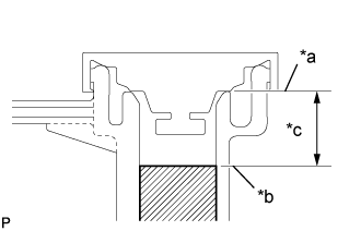 |
Slowly fill the radiator with TOYOTA Super Long Life Coolant (SLLC) from the water filler. (Coolant level should be within 20 mm (0.787 in.) from the filler tube end.)
| *a | Filler Tube End |
| *b | Coolant Level |
| *c | 20 mm |
Remove the reserve tank cap.
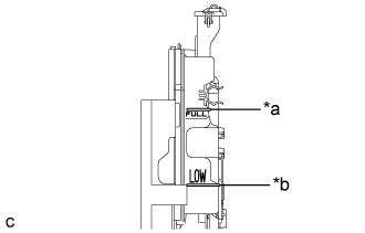 |
Slowly pour coolant into the radiator reserve tank assembly until it reaches the full line.
| *a | Full Line |
| *b | Low Line |
Squeeze the No. 1 and No. 2 radiator hoses several times by hand, and then check the level of the coolant.
If the coolant level is low, add coolant.
Install the water filler cap sub-assembly and reserve tank cap.
Put the engine in inspection mode (Click here).
Bleed air from the cooling system.
Warm up the engine until the thermostat opens. While the thermostat is open, circulate the coolant for several minutes.
Squeeze the No. 1 and No. 2 radiator hoses several times by hand to bleed air.
Stop the engine and wait until the engine coolant cools down.
Add engine coolant to the full line on the radiator reserve tank assembly.
| 41. ADD COOLANT (for Inverter) |
| DTC Code | Detection Item |
| P0A01-726 | Motor Electronics Coolant Temperature Sensor Circuit Range / Performance |
| P0A04-725 | Motor Electronics Coolant Temperature Sensor Circuit Intermittent |
| P0A08-264 | DC / DC Converter Status Circuit |
| P0A78-284 | Drive Motor "A" Inverter Performance |
| P0A78-286 | Drive Motor "A" Inverter Performance |
| P0A7A-322 | Generator Inverter Performance |
| P0A7A-324 | Generator Inverter Performance |
| P0A93-346 | Inverter Cooling System Performance |
| P0A94-553 | DC / DC Converter Performance |
| P0A94-557 | DC / DC Converter Performance |
| P0AEE-277 | Motor Inverter Temperature Sensor "A" Circuit Range / Performance |
| P0AF1-276 | Drive Motor Inverter Temperature Sensor "A" Circuit Intermittent / Erratic |
| P0BCD-315 | Generator Inverter Temperature Sensor Circuit Range / Performance |
| P0BD0-314 | Generator Inverter Temperature Sensor Circuit Intermittent / Erratic |
| P0C39-626 | DC / DC Converter Temperature Sensor "A" Range / Performance |
| P0C3C-625 | DC / DC Converter Temperature Sensor "A" Intermittent / Erratic |
| P0C3E-628 | DC / DC Converter Temperature Sensor "B" Range / Performance |
| P0C41-627 | DC / DC Converter Temperature Sensor "B" Intermittent / Erratic |
| P0C73-776 | Motor Electronics Coolant Pump "A" Control Performance |
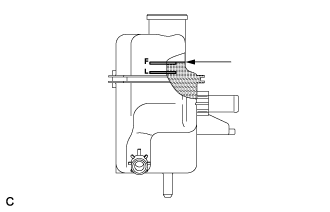 |
Slowly pour coolant into the reserve tank until it reaches the full line.
When using the intelligent tester:
Connect the intelligent tester to the DLC3.
Turn the power switch on (IG).
Enter the following menus: Powertrain / Hybrid Control / Active Test / Activate the Water Pump.
Keep the coolant at the full line in the reserve tank to compensate for the drop in coolant level when the air bleeds.
When not using the intelligent tester:
Turn the power switch on (READY). [*1]
Turn the power switch off and add coolant to the full line because the coolant level drops as the air bleeds. [*2]
Repeat steps [*1] and [*2] until air bleeding from the cooling system is completed.
After the air is completely bled from the cooling system, tighten the reserve tank cap.
|
Add coolant to the full line of the reserve tank.
| 42. ADD HYBRID TRANSAXLE FLUID |
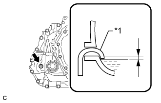 |
Add transaxle fluid until the fluid level is between 0 to 8 mm (0 to 0.315 in.) from the bottom lip of the filler plug opening.
| *1 | Filler Nozzle |
After adding fluid, leave it for 30 seconds so that the fluid surface can become still again, and then check that the fluid level is between 0 to 8 mm (0 to 0.315 in.) from the bottom lip of the filler plug opening. (If the fluid level is too low, return to the Add Hybrid Transaxle Fluid procedure.)
Using a 10 mm hexagon socket wrench, temporarily install the filler plug and gasket.
| 43. INSPECT HYBRID TRANSAXLE FLUID |
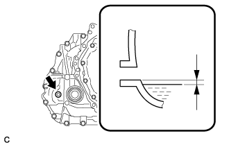 |
Using a 10 mm hexagon socket wrench, remove the filler plug and gasket.
Check that the fluid level is between 0 to 8 mm (0 to 0.315 in.) from the bottom lip of the filler plug opening. (If the fluid level is too low, return to the Add Hybrid Transaxle Fluid procedure.)
Check for leaks if the quantity of transaxle fluid is low. (If there are no fluid leaks but the amount of the fluid is insufficient, add fluid .
Using a 10 mm hexagon socket wrench, install the filler plug with a new gasket.
| 44. INSPECT FOR COOLANT LEAK (for Engine) |
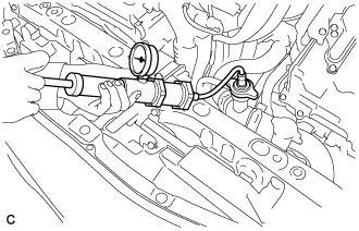 |
Fill the radiator with coolant and attach a radiator cap tester.
Put the engine in inspection mode (Click here).
Warm up the engine.
Using a radiator cap tester, increase the pressure inside the radiator to 108 kPa (1.1 kgf/cm2, 16 psi), and check that the pressure does not drop.
If the pressure drops, check the hoses, radiator, engine water pump, front exhaust pipe assembly and engine coolant temperature sensor for leaks. If no external leaks are found, check the heater core, cylinder block and cylinder head.
| 45. INSPECT FOR COOLANT LEAK (for Inverter) |
Remove the reserve tank cap.
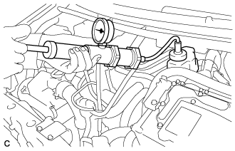 |
Install a radiator cap tester.
Pump the radiator cap tester to 122 kPa (1.2 kgf/ cm2, 18 psi), and then check that the pressure does not drop.
Reinstall the reserve tank cap.
| 46. INSPECT FOR HYBRID TRANSAXLE FLUID LEAK |
| 47. INSPECT FOR EXHAUST GAS LEAK |
| 48. INSTALL FRONT WHEELS |
| 49. INSPECT SHIFT LEVER POSITION SENSOR POSITION |
Apply the parking brake.
Lock the wheels with chocks to secure the vehicle.
Turn the power switch on (READY).
Move the shift lever to D and release the brake.
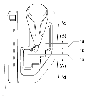 |
Slowly move the shift lever to N and measure moving distance (A) of the shift lever from the original point to the gear disengagement point.
| *a | Gear Disengagement Point |
| *b | N Position |
| *c | R Position |
| *d | D Position |
Move the shift lever to R and release the brake.
Slowly move the shift lever to N and measure moving distance (B) of the shift lever from the original point to the vehicle disengagement point.
Check that moving distances (A) and (B) shown in the illustration are almost the same.
| 50. ADJUST SHIFT LEVER POSITION SENSOR POSITION |
If moving distance (A) is shorter than (B). [*1]
Move the shift lever to N.
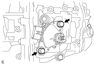 |
Loosen the 2 bolts.
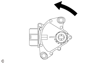 |
Slightly turn the shift lever position sensor counterclockwise.
|
Tighten the 2 bolts in the order shown in the illustration.
Recheck the shift lever position sensor.
If moving distance (B) is shorter than (A). [*2]
Move the shift lever to N.
|
Loosen the 2 bolts.
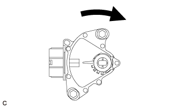 |
Slightly turn the shift lever position sensor clockwise.
|
Tighten the 2 bolts in the order shown in the illustration.
Recheck the shift lever position sensor.
| 51. INSPECT SHIFT LEVER POSITION |
While moving the shift lever from N to each position, check that the lever moves smoothly and that the shift position indicator comes on properly according to the shift lever position.
Turn the power switch on (READY) and check the following:
When the shift lever is moved to D, the vehicle moves forward.
When the shift lever is moved to R, the vehicle moves in reverse.
| 52. ADJUST SHIFT LEVER POSITION |
Apply the parking brake and move the shift lever to N.
Remove the rear console box assembly (Click here).
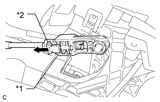 |
Slide the adjuster case cover in the direction shown by the arrow.
| *1 | Adjuster Case |
| *2 | Adjuster Case Cover |
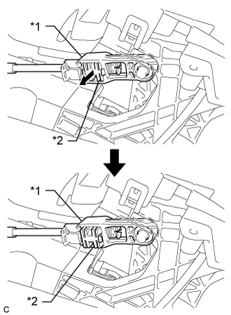 |
Using a precision screwdriver, pull out the lock piece of the adjuster case.
| *1 | Adjuster Case |
| *2 | Lock Piece |
Using your fingers, gently pull the cable rod towards the rear of the vehicle to remove backlash.
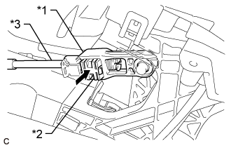 |
Push in the lock piece of the adjuster case to lock it.
| *1 | Adjuster Case |
| *2 | Lock Piece |
| *3 | Cable Rod |
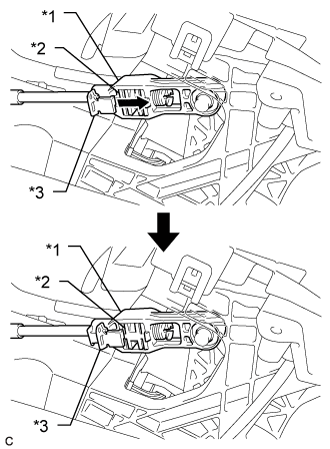 |
Move the adjuster case cover in the direction shown by the arrow.
| *1 | Adjuster Case |
| *2 | Lock Piece |
| *3 | Adjuster Case Cover |
Install the rear console box assembly (Click here).
| 53. INSTALL ENGINE UNDER COVER RH |
| 54. INSTALL ENGINE UNDER COVER LH |
| 55. INSPECT AND ADJUST FRONT WHEEL ALIGNMENT |
| 56. CHECK ABS SPEED SENSOR SIGNAL |