CAN COMMUNICATION SYSTEM > DIAGNOSIS SYSTEM |
| ECUS OR SENSORS WHICH COMMUNICATE THROUGH CAN COMMUNICATION SYSTEM |
V Bus
ECM
Brake booster with master cylinder assembly (Skid control ECU)
Main body ECU (Multiplex network body ECU)
Air conditioning amplifier assembly
Power steering ECU assembly
Smart key ECU assembly (Certification ECU)
Airbag sensor assembly
Spiral cable with sensor sub-assembly (Steering sensor)
Hybrid vehicle control computer assembly
Combination meter assembly
Sub Bus 15
ECM
Brake booster with master cylinder assembly (Skid control ECU)
Hybrid vehicle control computer assembly
| CHECK FOR INSTALLED SYSTEMS (ECUS AND SENSORS) THAT USE CAN COMMUNICATION |
The systems (ECUs and sensors) that use CAN communication vary depending on the vehicle and optional equipment. Check which systems (ECUs and sensors) are installed on the vehicle.
| ECU/Sensor Name | GTS Display | Applicability |
| ECM | ECM (Engine) | Installed on all vehicles |
| Main body ECU (Multiplex network body ECU) | Main Body | Installed on all vehicles |
| Brake booster with master cylinder assembly (Skid control ECU) | Skid Control (ABS/VSC/TRAC) | Installed on all vehicles |
| Power steering ECU assembly | Power Steering (EPS) | Installed on all vehicles |
| Air conditioning amplifier assembly | Air Conditioning Amplifier | Installed on all vehicles |
| Airbag sensor assembly | Airbag | Installed on all vehicles |
| Smart key ECU assembly (Certification ECU) | Certification (Smart) | Installed on all vehicles |
| Hybrid vehicle control computer assembly | Hybrid Vehicle Control | Installed on all vehicles |
| Spiral cable with sensor sub-assembly (Steering sensor) | Spiral cable (Steering Angle Sensor) | Installed on all vehicles |
| Combination meter assembly | Combination Meter | Installed on all vehicles |
| CAN BUS CHECK |
Using the GTS, select the CAN Bus Check screen.
| Bus Type | Background Color | Connection Status |
| V Bus | White | Communication has been normal since the start of the CAN bus check. |
| Yellow | Communication stop occurred at least once since the start of the CAN bus check, but communication is currently occurring (unstable communication). | |
| Red | Communication was established at least once since the start of the CAN bus check, but communication is currently not occurring (unstable communication). | |
| Not displayed | Communication stop has continued since the start of the CAN bus check.*1 | |
| Sub Bus (gateway function equipped ECU that does not have history of connected ECUs)*2 | White | Communication has been normal since the start of the CAN bus check. |
| Yellow | Communication stop occurred at least once since the start of the CAN bus check, but communication is currently occurring (unstable communication). | |
| Red | Communication was established at least once since the start of the CAN bus check, but communication is currently not occurring (unstable communication). | |
| Not displayed | Communication stop has continued since the start of the CAN bus check.*1 | |
| Sub Bus (gateway function equipped ECU that has history of connected ECUs)*3 | White | Communication has been normal since the start of the CAN bus check. |
| Yellow | Communication stop occurred at least once since the start of the CAN bus check, but communication is currently occurring (unstable communication). | |
| Red | Currently not communicating (either of the following):
| |
| Not displayed | Either of the following:
|
Observe the connection response screen for approximately 2 minutes to check for a change in connection status of the connected ECUs and sensors.
| HOW TO INTERPRET CAN BUS CHECK SCREEN |
When a communication stop is currently occurring, the probable malfunctioning part can be determined from the CAN bus check and by using the following methods.
If a communication error of only 1 ECU or sensor is indicated on the CAN Bus Check screen, a communication stop of the ECU or sensor is suspected.
Example: Open in both CAN branch lines of ECU B on the V bus
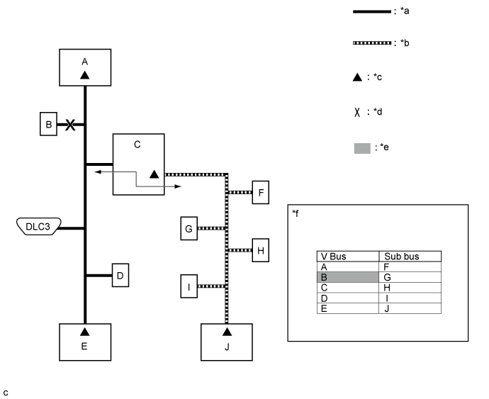
| *a | V Bus | *b | Sub Bus |
| *c | Terminating Resistor | *d | Location of Malfunction |
| *e | Not displayed or background color changes to red or yellow | *f | CAN Bus Check Screen |
![]() |
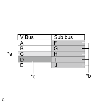
If communication errors for multiple ECUs or sensors are indicated on the CAN Bus Check screen, then a communication stop of the ECU or sensor that shows a more serious communication stop (an ECU or sensor which is not displayed) is suspected.
Example: Open in a CAN branch line for ECU D on the V bus
| *a | Background color periodically changes to yellow or red |
| *b | Not displayed or background color is yellow or red |
| *c | Not displayed |
| Bus Type | Background Color | Connection Status |
| V Bus | White | Communication has been normal since the start of the CAN bus check. |
| Yellow | Communication stop occurred at least once since the start of the CAN bus check, but communication is currently occurring (unstable communication). | |
| Red | Communication was established at least once since the start of the CAN bus check, but communication is currently not occurring (unstable communication). | |
| Not displayed | Communication stop has continued since the start of the CAN bus check.*1 | |
| Sub Bus (gateway function equipped ECU that does not have history of connected ECUs)*2 | White | Communication has been normal since the start of the CAN bus check. |
| Yellow | Communication stop occurred at least once since the start of the CAN bus check, but communication is currently occurring (unstable communication). | |
| Red | Communication was established at least once since the start of the CAN bus check, but communication is currently not occurring (unstable communication). | |
| Not displayed | Communication stop has continued since the start of the CAN bus check.*1 | |
| Sub Bus (gateway function equipped ECU that has history of connected ECUs)*3 | White | Communication has been normal since the start of the CAN bus check. |
| Yellow | Communication stop occurred at least once since the start of the CAN bus check, but communication is currently occurring (unstable communication). | |
| Red | Currently not communicating (either of the following):
| |
| Not displayed | Either of the following:
|
![]() |
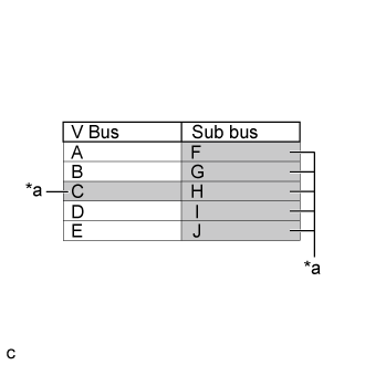
If a communication error is indicated on both the V bus and sub bus on the CAN Bus Check screen, suspect any communication stop displayed for the V bus first.
Example: Open in both CAN branch lines of ECU C on the V bus
| *a | Not displayed or background color changes to red |
![]() |
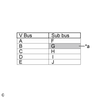
If the CAN Bus Check screen indicates a communication stop only in the sub bus, a communication stop in the sub bus is suspected.
Example: Open in both CAN branch lines of ECU G on the sub bus
| *a | Background color changes to red |
If both of the V bus main bus lines are open, ECUs or sensors that are located farther away from the DLC3 than the open part will be displayed as a communication stop on the CAN Bus Check screen.
(In this case, ECU A and B are not displayed or their background color changes to red.)
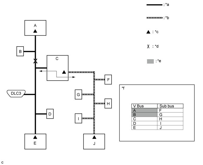
| *a | V Bus | *b | Sub Bus |
| *c | Terminating Resistor | *d | Location of Malfunction |
| *e | Not displayed or background color is red | *f | CAN Bus Check Screen |
If both of the sub bus main bus lines are open, ECUs that are located farther away from the gateway function equipped ECU than the open part will be displayed as a communication stop on the CAN Bus Check screen.
(In this case, ECU I and J are not displayed or their background color changes to red.)
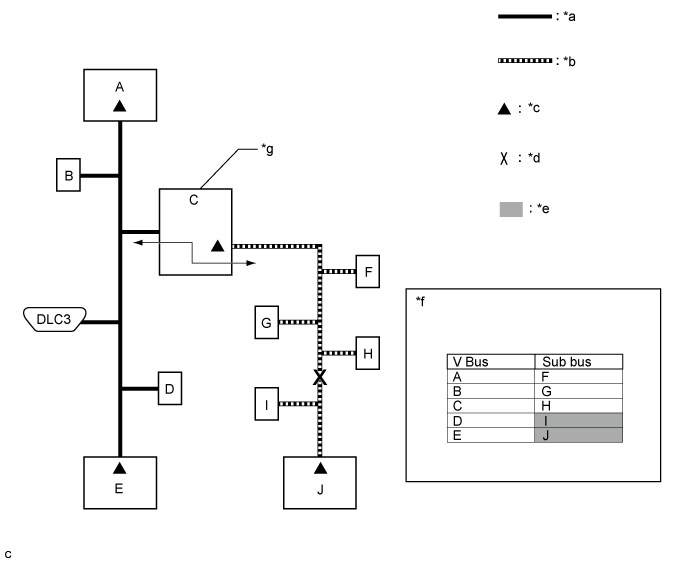
| *a | V Bus | *b | Sub Bus |
| *c | Terminating Resistor | *d | Location of Malfunction |
| *e | Not displayed or background color is red | *f | CAN Bus Check Screen |
| *g | Gateway Function Equipped ECU | - | - |
![]() |
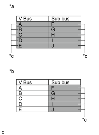
When any of the following malfunctions occur, CAN communication cannot be established and almost all ECUs and sensors on the bus show a communication error on the CAN Bus Check screen.
| *a | When any of the following malfunctions occur on the V bus |
| *b | When any of the following malfunctions occur on a sub bus |
| *c | Not displayed |
| Short between CAN lines (CANH and CANL) |
| Short between a CAN line (CANH or CANL) and +B |
| Short between a CAN line (CANH or CANL) and ground |
| Open in a CAN main bus line |
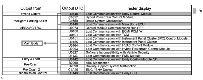
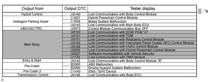
| HOW TO INTERPRET COMMUNICATION DTCS (DTCS THAT START WITH U) |
If a CAN communication error cannot be reproduced, determine the suspected malfunctioning part using the DTCs stored in ECUs that are connected to the CAN buses by following the procedure below.
If multiple ECUs store a communication DTC for a particular ECU, a communication stop of the ECU is suspected.

| *a | Items to be Checked | - | - |
If almost all of the communication DTCs of an ECU are stored, a communication stop of the ECU is suspected.

| *a | Items to be Checked | - | - |
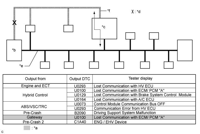
To help determine the part of the sub bus that has a communication error, prioritize the communication stop DTCs stored in the gateway function equipped ECU.

| *a | Items to be Checked | *b | ECM |
| *c | Gateway Function Equipped ECU | *d | Location of Malfunction |
| *e | V Bus | *f | Sub Bus |
When any of the following malfunctions occurs, many DTCs are likely to be output from many ECUs. Because of this, it may be difficult to determine the probable malfunctioning part.
| DTC TABLE BY ECU |
Hybrid Vehicle Control Computer Assembly / GTS Display "Hybrid Control"
| DTC | Detection Item | DTC Detection Condition | DTC Detection Pre-condition | DTC Check Procedure | Warning Indication in Meter | DTC Storage Method |
| U0100 | Lost Communication with ECM / PCM "A" | The hybrid vehicle control computer assembly (HV CPU) does not receive data from the ECM for 0.58 seconds or more. | Both conditions are met:
| Turn the power switch on (IG) and wait at least 1.58 seconds. |
| DTC is stored until it is cleared using the GTS. |
| U0110*1 | Lost Communication with Drive Motor Control Module "A" | Either condition is met:
| Both conditions are met:
| Turn the power switch on (IG) and wait at least 0.22 seconds. | Master warning light turns on. | DTC is stored until it is cleared using the GTS. |
| U0129 | Lost Communication with Brake System Control Module | The hybrid vehicle control computer assembly (HV CPU) does not receive data from the brake booster with master cylinder assembly (skid control ECU) for 2.34 seconds or more. | Both conditions are met:
| Turn the power switch on (IG) and wait at least 4.44 seconds. |
| DTC is stored until it is cleared using the GTS. |
| U0151 | Communication Error from Airbag ECU to HV ECU | The hybrid vehicle control computer assembly (HV CPU) does not receive data from the airbag sensor assembly for 10.6 seconds or more. | Both conditions are met:
| Turn the power switch on (IG) and wait at least 11.6 seconds. | Master warning light turns on. | DTC is stored until it is cleared using the GTS. |
| U0164 | Communication Error from A/C ECU to HV ECU | The hybrid vehicle control computer assembly (HV CPU) does not receive data from the air conditioning amplifier assembly for 10.6 seconds or more. | Both conditions are met:
| Turn the power switch on (IG) and wait at least 11.6 seconds. | - | DTC is stored until it is cleared using the GTS. |
| U029A*2 | Lost Communication with Hybrid Battery Pack Sensor Module | The hybrid vehicle control computer assembly (HV CPU) does not receive data from the battery smart unit for 0.52 seconds or more. | The power switch is on (IG) for 0.5 seconds or more. | Turn the power switch on (IG) and wait at least 1.02 seconds. |
| DTC is stored until it is cleared using the GTS. |
| U0424*1 | Invalid Data Received from HVAC Control Module | The hybrid vehicle control computer assembly (HV CPU) receives an abnormal operation value command from the air conditioning amplifier assembly for 3 seconds or more. | Both conditions are met:
| Turn the power switch on (IG) and wait at least 3.5 seconds. | - | DTC is stored until it is cleared using the GTS. |
| U1107 | Lost Communication with Power Management Module | The hybrid vehicle control computer assembly (HV CPU) does not receive data from the smart key ECU assembly (certification ECU) (power management CPU) for 3.6 seconds or more. | Both conditions are met:
| Turn the power switch on (IG) and wait at least 4.6 seconds. | Master warning light turns on. | DTC is stored until it is cleared using the GTS. |
Hybrid Vehicle Control Computer Assembly / GTS Display "Cruise Control"
| DTC | Detection Item | DTC Detection Condition | DTC Detection Pre-condition | DTC Check Procedure | Warning Indication in Meter | DTC Storage Method |
| U0122 | Lost Communication with Vehicle Dynamics Control Module | While the cruise control system is on (the system has been switched on using the ON/OFF button on the cruise control switch), the hybrid vehicle control computer assembly (HV CPU) does not receive data from the brake booster with master cylinder assembly (skid control ECU) for 2.62 seconds or more. | Both conditions are met:
| After turning the power switch on (IG), turn the cruise control main switch on and wait for at least 4.72 seconds. |
| DTC is stored until it is cleared using the GTS. |
ECM / GTS Display "Engine and ECT"
| DTC | Detection Item | DTC Detection Condition | DTC Detection Pre-condition | DTC Check Procedure | Warning Indication in Meter | DTC Storage Method |
| U0293 | Lost Communication with HV ECU | The ECM does not receive data from the hybrid vehicle control computer assembly (HV CPU) for 0.576 seconds or more. | Both conditions are met:
| Turn the power switch on (IG) and wait at least 1.576 seconds. | MIL illuminates. | DTC is stored until it is cleared using the GTS. |
Power Steering ECU Assembly / GTS Display "EMPS"
| DTC | Detection Item | DTC Detection Condition | DTC Detection Pre-condition | DTC Check Procedure | Warning Indication in Meter | DTC Storage Method |
| U0129 | Lost Communication with Brake System Control Module | The power steering ECU assembly cannot receive data from the brake booster with master cylinder assembly (skid control ECU) for 2.34 seconds or more. | Both conditions are met:
| Turn the power switch on (IG) and wait at least 4.34 seconds. | EPS warning light illuminates. | DTC remains stored only while malfunction is occurring. |
| U0293 | Lost Communication with Hybrid Control Module | The power steering ECU assembly cannot receive data from the hybrid vehicle control computer assembly (HV CPU) for 5 minutes or more. | Both conditions are met:
| Drive the vehicle at a speed of 20 km/h (12 mph) or more for at least 5 minutes. | EPS warning light illuminates. | DTC remains stored only while malfunction is occurring. |
Brake Booster with Master Cylinder Assembly (Skid Control ECU) / GTS Display "ABS/VSC/TRC"
| DTC | Detection Item | DTC Detection Condition | DTC Detection Pre-condition | DTC Check Procedure | Warning Indication in Meter | DTC Storage Method |
| U0073 | Control Module Communication Bus OFF | One of the following conditions is met:
| Both conditions are met:
| Turn the power switch on (IG) and wait at least 60 seconds. | <When data can be sent to the combination meter>
| DTC is stored until it is cleared using the GTS. |
<When data cannot be sent to the combination meter>
| ||||||
| U0120 | Lost Communication with Yaw Rate Sensor Module | The brake booster with master cylinder assembly (skid control ECU) cannot receive data from the smart key ECU assembly (certification ECU) for 3 seconds or more. | Both conditions are met:
| Turn the power switch on (IG) and wait at least 4 seconds. | Brake warning light / yellow (minor malfunction) illuminates. | DTC is stored until it is cleared using the GTS. |
| U0123 | Lost Communication with Yaw Rate Sensor Module | Either of the following conditions is met:
| Both conditions are met:
| Turn the power switch on (IG) and wait at least 60 seconds. |
| DTC is stored until it is cleared using the GTS. |
| U0124 | Lost Communication with Lateral Acceleration Sensor Module | Either of the following conditions is met:
| Both conditions are met:
| Turn the power switch on (IG) and wait at least 60 seconds. |
| DTC is stored until it is cleared using the GTS. |
| U0126 | Lost Communication with Steering Angle Sensor Module | Either of the following conditions is met:
| Both conditions are met:
| Turn the power switch on (IG) and wait at least 60 seconds. | Slip warning light illuminates. | DTC is stored until it is cleared using the GTS. |
| U0293 | Communication Error from HV ECU | Either of the following conditions is met:
| Both conditions are met:
| Turn the power switch on (IG) and wait at least 60 seconds. |
| DTC is stored until it is cleared using the GTS. |
Spiral Cable with Sensor Sub-assembly (Steering sensor) / GTS Display "-"
Airbag Sensor Assembly / GTS Display "Airbag"
Main Body ECU (Multiplex Network Body ECU) / GTS Display "Main Body"
| DTC | Detection Item | DTC Detection Condition | DTC Detection Pre-condition | DTC Check Procedure | Warning Indication in Meter | DTC Storage Method |
| U0100 | Lost Communication with ECM / PCM "A" | The main body ECU (multiplex network body ECU) does not receive data from the ECM for 10 seconds or more. | Both conditions are met:
| Turn the power switch on (IG) and wait at least 20 seconds. | - | DTC is stored until it is cleared using the GTS. |
| U0101 | Lost Communication with ECT | The main body ECU (multiplex network body ECU) does not receive data from the hybrid vehicle control computer assembly (HV CPU) for 10 seconds or more. | Both conditions are met:
| Turn the power switch on (IG) and wait at least 20 seconds. | - | DTC is stored until it is cleared using the GTS. |
| U0120 | Lost Communication With Starter / Generator Control Module | The main body ECU (multiplex network body ECU) does not receive data from the smart key ECU assembly (certification ECU) (power management CPU) for 10 seconds or more. | Both conditions are met:
| Turn the power switch on (IG) and wait at least 20 seconds. | - | DTC is stored until it is cleared using the GTS. |
| U0151 | Communication Error from Airbag ECU to HV ECU | The main body ECU (multiplex network body ECU) does not receive data from the airbag sensor assembly for 10 seconds or more. | Both conditions are met:
| Turn the power switch on (IG) and wait at least 20 seconds. | - | DTC is stored until it is cleared using the GTS. |
| U0155 | Lost Communication with Combination Meter | The main body ECU (multiplex network body ECU) does not receive data from the combination meter assembly for 10 seconds or more. | Both conditions are met:
| Turn the power switch on (IG) and wait at least 20 seconds. | - | DTC is stored until it is cleared using the GTS. |
| U0164 | Communication Error from A/C ECU to HV ECU | The main body ECU (multiplex network body ECU) does not receive data from the air conditioning amplifier assembly for 10 seconds or more. | Both conditions are met:
| Turn the power switch on (IG) and wait at least 20 seconds. | - | DTC is stored until it is cleared using the GTS. |
| U0293 | Communication Error from HV ECU | The main body ECU (multiplex network body ECU) does not receive data from the hybrid vehicle control computer assembly (HV CPU) for 10 seconds or more. | Both conditions are met:
| Turn the power switch on (IG) and wait at least 20 seconds. | - | DTC is stored until it is cleared using the GTS. |
| U0327 | Software Incompatibility with Vehicle Security Control Module | The main body ECU (multiplex network body ECU) does not receive data from the smart key ECU assembly (certification ECU) for 10 seconds or more. | Both conditions are met:
| Turn the power switch on (IG) and wait at least 20 seconds. | - | DTC is stored until it is cleared using the GTS. |
Smart Key ECU Assembly (Certification ECU) / GTS Display "Entry&Start"
| DTC | Detection Item | DTC Detection Condition | DTC Detection Pre-condition | DTC Check Procedure | Warning Indication in Meter | DTC Storage Method |
| U0100 | Lost Communication with ECM | The smart key ECU assembly (certification ECU) does not receive data from the ECM for 10 seconds or more. | Both conditions are met:
| Turn the power switch on (IG) and wait at least 20 seconds. | - | DTC is stored until it is cleared using the GTS. |
| U0142 | Lost Communication with Main Body ECU | The smart key ECU assembly (certification ECU) does not receive data from the main body ECU (multiplex network body ECU) for 10 seconds or more. | Both conditions are met:
| Turn the power switch on (IG) and wait at least 20 seconds. | - | DTC is stored until it is cleared using the GTS. |
| U0155 | Lost Communication with Combination Meter | The smart key ECU assembly (certification ECU) does not receive data from the combination meter assembly for 10 seconds or more. | Both conditions are met:
| Turn the power switch on (IG) and wait at least 20 seconds. | - | DTC is stored until it is cleared using the GTS. |
| U0293 | Lost Communication with HV ECU | The smart key ECU assembly (certification ECU) does not receive data from the hybrid vehicle control computer assembly (HV CPU) for 10 seconds or more. | Both conditions are met:
| Turn the power switch on (IG) and wait at least 20 seconds. | - | DTC is stored until it is cleared using the GTS. |
Smart Key ECU Assembly (Certification ECU) / GTS Display "Power Source Control"
| DTC | Detection Item | DTC Detection Condition | DTC Detection Pre-condition | DTC Check Procedure | Warning Indication in Meter | DTC Storage Method |
| U0140 | Lost Communication with Main Body ECU | The smart key ECU assembly (certification ECU) (power management CPU) does not receive data from the main body ECU (multiplex network body ECU) for 3.1 seconds or more. | Both conditions are met:
| Turn the power switch on (IG) and wait at least 13.1 seconds. | - | DTC is stored until it is cleared using the GTS. |
| U0155 | Lost Communication with Combination Meter | The smart key ECU assembly (certification ECU) (power management CPU) does not receive data from the combination meter assembly for 3.1 seconds or more. | Both conditions are met:
| Turn the power switch on (IG) and wait at least 13.1 seconds. | - | DTC is stored until it is cleared using the GTS. |
| U0293 | Lost Communication with HV ECU | The smart key ECU assembly (certification ECU) (power management CPU) does not receive data from the hybrid vehicle control computer assembly (HV CPU) for 3.1 seconds or more. | Both conditions are met:
| Turn the power switch on (IG) and wait at least 13.1 seconds. | - | DTC is stored until it is cleared using the GTS. |
Air Conditioning Amplifier Assembly / GTS Display "Air Conditioner"
| DTC | Detection Item | DTC Detection Condition | DTC Detection Pre-condition | DTC Check Procedure | Warning Indication in Meter | DTC Storage Method |
| U0101 | Lost Communication With TCM | The air conditioning amplifier assembly does not receive data from the hybrid vehicle control computer assembly (HV CPU) for 5 seconds or more. | Both conditions are met:
| Turn the power switch on (IG) and wait at least 5 seconds. | - | DTC is stored until it is cleared using the GTS. |
| U0142 | Lost Communication with Main Body ECU | The air conditioning amplifier assembly does not receive data from the main body ECU (multiplex network body ECU) for 5 seconds or more. | Both conditions are met:
| Turn the power switch on (IG) and wait at least 5 seconds. | - | DTC is stored until it is cleared using the GTS. |
| U0155 | Lost Communication with Combination Meter | The air conditioning amplifier assembly does not receive data from the combination meter assembly for 5 seconds or more. | Both conditions are met:
| Turn the power switch on (IG) and wait at least 5 seconds. | - | DTC is stored until it is cleared using the GTS. |
| U0293 | Lost Communication with HV ECU | The air conditioning amplifier assembly does not receive data from the hybrid vehicle control computer assembly (HV CPU) for 5 seconds or more. | Both conditions are met:
| Turn the power switch on (IG) and wait at least 5 seconds. | - | DTC is stored until it is cleared using the GTS. |
Combination Meter Assembly / GTS Display "Combination Meter"
| DTC | Detection Item | DTC Detection Condition | DTC Detection Pre-condition | DTC Check Procedure | Warning Indication in Meter | DTC Storage Method |
| U0100 | Lost Communication with ECM / PCM "A" | The combination meter assembly does not receive data from the ECM for 2 seconds or more. | Both conditions are met:
| Turn the power switch on (IG) and wait at least 2 seconds. | - | DTC is stored until it is cleared using the GTS. |
| U0129 | Lost Communication with Skid Control ECU | The combination meter assembly does not receive data from the brake booster with master cylinder assembly (skid control ECU) for 3 seconds or more. | Both conditions are met:
| Turn the power switch on (IG) and wait at least 3 seconds. | - | DTC is stored until it is cleared using the GTS. |
| U0131 | Lost Communication with Power Steering Control Module | The combination meter assembly does not receive data from the power steering ECU assembly for 3 seconds or more. | Both conditions are met:
| Turn the power switch on (IG) and wait at least 3 seconds. | EPS warning light illuminates. | DTC is stored until it is cleared using the GTS. |
| U0142 | Lost Communication with Main Body ECU | The combination meter assembly does not receive data from the main body ECU (multiplex network body ECU) for 3 seconds or more. | Both conditions are met:
| Turn the power switch on (IG) and wait at least 3 seconds. | - | DTC is stored until it is cleared using the GTS. |
| U0151 | Lost Communication with Airbag ECU | The combination meter assembly does not receive data from the airbag sensor assembly for 10 seconds or more. | Both conditions are met:
| Turn the power switch on (IG) and wait at least 10 seconds. | SRS warning light illuminates. | DTC is stored until it is cleared using the GTS. |
| DTC COMBINATION TABLE (OPEN OR SHORT IN V BUS, PAST COMMUNICATION ERROR) |
Regarding the past communication error of an ECU and sensor connected to the V bus (in this case, normal is displayed when performing the CAN bus check, but communication DTCs are output), the probable CAN bus line(s) that had a malfunction can be determined based on the following DTC combination table.
| - | Trouble Mode (Open in Both CAN Branch Lines) | ||||
| V Bus | |||||
| Output ECU | Output DTC | Center Airbag Sensor Communication Stop Mode (Click here) | Air Conditioning Amplifier Communication Stop Mode (Click here) | Main Body ECU Communication Stop Mode (Click here) | |
| V Bus | Airbag Sensor Assembly | - | - | - | - |
| Air Conditioning Amplifier Assembly | U0101 | - | ○ | - | |
| U0142 | - | ○ | ○ | ||
| U0155 | - | ○ | - | ||
| U0293 | - | ○ | - | ||
| V Bus | Main Body ECU (Multiplex Network Body ECU) | U0100 | - | - | ○ |
| U0101 | - | - | ○ | ||
| U0120 | - | - | ○ | ||
| U0151 | ○ | - | ○ | ||
| U0155 | - | - | ○ | ||
| U0164 | - | ○ | ○ | ||
| U0293 | - | - | ○ | ||
| U0327 | - | - | ○ | ||
| Brake Booster with Master Cylinder Assembly (Skid Control ECU)* | U0120 | - | - | - | |
| U0123 | ○ | - | - | ||
| U0124 | ○ | - | - | ||
| U0126 | - | - | - | ||
| U0293 | - | - | - | ||
| Hybrid Vehicle Control Computer Assembly (HV CPU) | U0100 | - | - | - | |
| U0129 | - | - | - | ||
| U0151 | ○ | - | - | ||
| U0164 | - | ○ | - | ||
| U1107 | - | - | - | ||
| Hybrid Vehicle Control Computer Assembly (Cruise Control) | U0122 | - | - | - | |
| Smart Key ECU Assembly (Certification ECU) (Power Management CPU) | U0140 | - | - | ○ | |
| U0155 | - | - | - | ||
| U0293 | - | - | - | ||
| Power Steering ECU Assembly | U0129 | - | - | - | |
| U0293 | - | - | - | ||
| ECM | U0293 | - | - | - | |
| Smart Key ECU Assembly (Certification ECU) | U0100 | - | - | - | |
| U0142 | - | - | ○ | ||
| U0155 | - | - | - | ||
| U0293 | - | - | - | ||
| Combination Meter Assembly | U0100 | - | - | - | |
| U0129 | - | - | - | ||
| U0131 | - | - | - | ||
| U0142 | - | - | ○ | ||
| U0151 | ○ | - | - | ||
| Spiral Cable with Sensor Sub-assembly (Steering Sensor) | - | - | - | - | |
| - | Trouble Mode (Open in Both CAN Branch Lines) | ||||
| V Bus | |||||
| Output ECU | Output DTC | Skid Control ECU Communication Stop Mode (Click here) | Hybrid Vehicle Control ECU Communication Stop Mode (Click here) | Power Steering ECU Communication Stop Mode (Click here) | |
| V Bus | Airbag Sensor Assembly | - | - | - | - |
| Air Conditioning Amplifier Assembly | U0101 | - | - | - | |
| U0142 | - | - | - | ||
| U0155 | - | - | - | ||
| U0293 | - | ○ | - | ||
| Main Body ECU (Multiplex Network Body ECU) | U0100 | - | - | - | |
| U0101 | - | - | - | ||
| U0120 | - | ○ | - | ||
| U0151 | - | - | - | ||
| U0155 | - | - | - | ||
| U0164 | - | - | - | ||
| U0293 | - | ○ | - | ||
| U0327 | - | - | - | ||
| Brake Booster with Master Cylinder Assembly (Skid Control ECU)* | U0120 | ○ | - | - | |
| U0123 | ○ | - | - | ||
| U0124 | ○ | - | - | ||
| U0126 | ○ | - | - | ||
| U0293 | ○ | ○ | - | ||
| Hybrid Vehicle Control Computer Assembly (HV CPU) | U0100 | - | - | ○ | |
| U0129 | ○ | ○ | - | ||
| U0151 | - | ○ | - | ||
| U0164 | - | ○ | - | ||
| U1107 | - | ○ | - | ||
| Hybrid Vehicle Control Computer Assembly (Cruise Control) | U0122 | ○ | ○ | - | |
| Smart Key ECU Assembly (Certification ECU) (Power Management CPU) | U0140 | - | - | - | |
| U0155 | - | - | - | ||
| U0293 | - | ○ | - | ||
| Power Steering ECU Assembly | U0129 | ○ | - | ○ | |
| U0293 | - | ○ | ○ | ||
| ECM | U0293 | - | ○ | - | |
| Smart Key ECU Assembly (Certification ECU) | U0100 | - | - | - | |
| U0142 | - | - | - | ||
| U0155 | - | - | - | ||
| U0293 | - | ○ | - | ||
| Combination Meter Assembly | U0100 | - | - | - | |
| U0129 | ○ | - | - | ||
| U0131 | - | - | ○ | ||
| U0142 | - | - | - | ||
| U0151 | - | - | - | ||
| V Bus | Spiral Cable with Sensor Sub-assembly (Steering Sensor) | - | - | - | - |
| - | Trouble Mode (Open in Both CAN Branch Lines) | ||||
| V Bus | |||||
| Output ECU | Output DTC | Certification ECU Communication Stop Mode (Click here) | Steering Angle Sensor Communication Stop Mode (Click here) | DLC3 | |
| V Bus | Airbag Sensor Assembly | - | - | - | - |
| Air Conditioning Amplifier Assembly | U0101 | - | - | - | |
| U0142 | - | - | - | ||
| U0155 | - | - | - | ||
| U0293 | - | - | - | ||
| Main Body ECU (Multiplex Network Body ECU) | U0100 | - | - | - | |
| U0101 | - | - | - | ||
| U0120 | - | - | - | ||
| U0151 | - | - | - | ||
| U0155 | - | - | - | ||
| U0164 | - | - | - | ||
| U0293 | - | - | - | ||
| U0327 | ○ | - | - | ||
| Brake Booster with Master Cylinder Assembly (Skid Control ECU)* | U0120 | ○ | - | - | |
| U0123 | - | - | - | ||
| U0124 | - | - | - | ||
| U0126 | - | ○ | - | ||
| U0293 | - | - | - | ||
| Hybrid Vehicle Control Computer Assembly (HV CPU) | U0100 | - | - | - | |
| U0129 | - | - | - | ||
| U0151 | - | - | - | ||
| U0164 | - | - | - | ||
| U1107 | - | - | - | ||
| Hybrid Vehicle Control Computer Assembly (Cruise Control) | U0122 | - | - | - | |
| Smart Key ECU Assembly (Certification ECU) (Power Management CPU) | U0140 | ○ | - | - | |
| U0155 | ○ | - | - | ||
| U0293 | - | - | - | ||
| Power Steering ECU Assembly | U0129 | - | - | - | |
| U0293 | - | - | - | ||
| ECM | U0293 | - | - | - | |
| V Bus | Smart Key ECU Assembly (Certification ECU) | U0100 | ○ | - | - |
| U0142 | ○ | - | - | ||
| U0155 | ○ | - | - | ||
| U0293 | ○ | - | - | ||
| Combination Meter Assembly | U0100 | - | - | - | |
| U0129 | - | - | - | ||
| U0131 | - | - | - | ||
| U0142 | - | - | - | ||
| U0151 | - | - | - | ||
| Spiral Cable with Sensor Sub-assembly (Steering Sensor) | - | - | - | - | |
| - | Trouble Mode (Open in Both CAN Main Bus Lines) | ||||
| V Bus | |||||
| Output ECU | Output DTC | ECM Communication Stop Mode (Click here) | CAN J/C LH to CAN J/C RH | Combination Meter ECU Communication Stop Mode (Click here) | |
| V Bus | Airbag Sensor Assembly | - | - | - | - |
| Air Conditioning Amplifier Assembly | U0101 | ○ | ○ | - | |
| U0142 | - | ○ | - | ||
| U0155 | - | - | ○ | ||
| U0293 | - | ○ | - | ||
| Main Body ECU (Multiplex Network Body ECU) | U0100 | ○ | - | - | |
| U0101 | ○ | - | - | ||
| U0120 | - | - | - | ||
| U0151 | - | ○ | - | ||
| U0155 | - | ○ | ○ | ||
| U0164 | - | ○ | - | ||
| U0293 | - | - | - | ||
| U0327 | - | ○ | - | ||
| Brake Booster with Master Cylinder Assembly (Skid Control ECU)* | U0120 | - | - | - | |
| U0123 | - | ○ | - | ||
| U0124 | - | ○ | - - | ||
| U0126 | - | ○ | - | ||
| U0293 | - | - | - | ||
| V Bus | Hybrid Vehicle Control Computer Assembly (HV CPU) | U0100 | ○ | - | - |
| U0129 | - | - | - | ||
| U0151 | - | ○ | - | ||
| U0164 | - | ○ | - | ||
| U1107 | - | - | - | ||
| Hybrid Vehicle Control Computer Assembly (Cruise Control) | U0122 | - | - | - | |
| Smart Key ECU Assembly (Certification ECU) (Power Management CPU) | U0140 | - | ○ | - | |
| U0155 | - | - | ○ | ||
| U0293 | - | - | - | ||
| Power Steering ECU Assembly | U0129 | - | - | - | |
| U0293 | - | - | - | ||
| ECM | U0293 | ○ | - | - | |
| Smart Key ECU Assembly (Certification ECU) | U0100 | ○ | ○ | - | |
| U0142 | - | ○ | - | ||
| U0155 | - | - | ○ | ||
| U0293 | - | ○ | - | ||
| Combination Meter Assembly | U0100 | ○ | ○ | - | |
| U0129 | - | ○ | - | ||
| U0131 | - | ○ | - | ||
| U0142 | - | ○ | - | ||
| U0151 | - | - | - | ||
| Spiral Cable with Sensor Sub-assembly (Steering Sensor) | - | - | - | - | |
| - | Trouble Mode (CAN Bus Line Short Circuit or Short to GND) | ||||
| V Bus | |||||
| Output ECU | Output DTC | CANH to CANL | CANH to GND | CANL to GND | |
| V Bus | Airbag Sensor Assembly | - | - | - | - |
| Air Conditioning Amplifier Assembly | U0101 | ○ | ○ | ○ | |
| U0142 | ○ | ○ | ○ | ||
| U0155 | ○ | ○ | ○ | ||
| U0293 | ○ | ○ | ○ | ||
| V Bus | Main Body ECU (Multiplex Network Body ECU) | U0100 | ○ | ○ | ○ |
| U0101 | ○ | ○ | ○ | ||
| U0120 | ○ | ○ | ○ | ||
| U0151 | ○ | ○ | ○ | ||
| U0155 | ○ | ○ | ○ | ||
| U0164 | ○ | ○ | ○ | ||
| U0293 | ○ | ○ | ○ | ||
| U0327 | ○ | ○ | ○ | ||
| Brake Booster with Master Cylinder Assembly (Skid Control ECU)* | U0120 | ○ | ○ | ○ | |
| U0123 | ○ | ○ | ○ | ||
| U0124 | ○ | ○ | ○ | ||
| U0126 | ○ | ○ | ○ | ||
| U0293 | ○ | ○ | ○ | ||
| Hybrid Vehicle Control Computer Assembly (HV CPU) | U0100 | ○ | ○ | ○ | |
| U0129 | ○ | ○ | ○ | ||
| U0151 | ○ | ○ | ○ | ||
| U0164 | ○ | ○ | ○ | ||
| U1107 | ○ | ○ | ○ | ||
| Hybrid Vehicle Control Computer Assembly (Cruise Control) | U0122 | ○ | ○ | ○ | |
| Smart Key ECU Assembly (Certification ECU) (Power Management CPU) | U0140 | ○ | ○ | ○ | |
| U0155 | ○ | ○ | ○ | ||
| U0293 | ○ | ○ | ○ | ||
| Power Steering ECU Assembly | U0129 | ○ | ○ | ○ | |
| U0293 | ○ | ○ | ○ | ||
| ECM | U0293 | ○ | ○ | ○ | |
| Smart Key ECU Assembly (Certification ECU) | U0100 | ○ | ○ | ○ | |
| U0142 | ○ | ○ | ○ | ||
| U0155 | ○ | ○ | ○ | ||
| U0293 | ○ | ○ | ○ | ||
| Combination Meter Assembly | U0100 | ○ | ○ | ○ | |
| U0129 | ○ | ○ | ○ | ||
| U0131 | ○ | ○ | ○ | ||
| U0142 | ○ | ○ | ○ | ||
| U0151 | ○ | ○ | ○ | ||
| Spiral Cable with Sensor Sub-assembly (Steering Sensor) | - | - | - | - | |
| - | Trouble Mode (Open in Both CAN Branch Lines) | ||||
| V Bus | |||||
| Output ECU | Output DTC | Center Airbag Sensor Communication Stop Mode (Click here) | Air Conditioning Amplifier Communication Stop Mode (Click here) | Main Body ECU Communication Stop Mode (Click here) | |
| V Bus | Airbag Sensor Assembly | - | - | - | - |
| Air Conditioning Amplifier Assembly | U0101 | - | ○ | - | |
| U0142 | - | ○ | ○ | ||
| U0155 | - | ○ | - | ||
| U0293 | - | ○ | - | ||
| Main Body ECU (Multiplex Network Body ECU) | U0100 | - | - | ○ | |
| U0101 | - | - | ○ | ||
| U0120 | - | - | ○ | ||
| U0151 | ○ | - | ○ | ||
| U0155 | - | - | ○ | ||
| U0164 | - | ○ | ○ | ||
| U0293 | - | - | ○ | ||
| U0327 | - | - | ○ | ||
| Brake Booster with Master Cylinder Assembly (Skid Control ECU)* | U0120 | - | - | - | |
| U0123 | ○ | - | - | ||
| U0124 | ○ | - | - | ||
| U0126 | - | - | - | ||
| U0293 | - | - | - | ||
| Hybrid Vehicle Control Computer Assembly (HV CPU) | U0100 | - | - | - | |
| U0129 | - | - | - | ||
| U0151 | ○ | - | - | ||
| U0164 | - | ○ | - | ||
| U1107 | - | - | - | ||
| Hybrid Vehicle Control Computer Assembly (Cruise Control) | U0122 | - | - | - | |
| Smart Key ECU Assembly (Certification ECU) (Power Management CPU) | U0140 | - | - | ○ | |
| U0155 | - | - | - | ||
| U0293 | - | - | - | ||
| Power Steering ECU Assembly | U0129 | - | - | - | |
| U0293 | - | - | - | ||
| ECM | U0293 | - | - | - | |
| Smart Key ECU Assembly (Certification ECU) | U0100 | - | - | - | |
| U0142 | - | - | ○ | ||
| U0155 | - | - | - | ||
| U0293 | - | - | - | ||
| Combination Meter Assembly | U0100 | - | - | - | |
| U0129 | - | - | - | ||
| U0131 | - | - | - | ||
| U0142 | - | - | ○ | ||
| U0151 | ○ | - | - | ||
| V Bus | Spiral Cable with Sensor Sub-assembly (Steering Sensor) | - | - | - | - |
| - | Trouble Mode (Open in Both CAN Branch Lines) | ||||
| V Bus | |||||
| Output ECU | Output DTC | Skid Control ECU Communication Stop Mode (Click here) | Hybrid Vehicle Control ECU Communication Stop Mode (Click here) | Power Steering ECU Communication Stop Mode (Click here) | |
| V Bus | Airbag Sensor Assembly | - | - | - | - |
| Air Conditioning Amplifier Assembly | U0101 | - | - | - | |
| U0142 | - | - | - | ||
| U0155 | - | - | - | ||
| U0293 | - | ○ | - | ||
| Main Body ECU (Multiplex Network Body ECU) | U0100 | - | - | - | |
| U0101 | - | - | - | ||
| U0120 | - | - | - | ||
| U0151 | - | - | - | ||
| U0155 | - | - | - | ||
| U0164 | - | - | - | ||
| U0293 | - | ○ | - | ||
| U0327 | - | - | - | ||
| Brake Booster with Master Cylinder Assembly (Skid Control ECU)* | U0120 | ○ | - | - | |
| U0123 | ○ | - | - | ||
| U0124 | ○ | - | - | ||
| U0126 | ○ | - | - | ||
| U0293 | ○ | ○ | - | ||
| Hybrid Vehicle Control Computer Assembly (HV CPU) | U0100 | - | ○ | - | |
| U0129 | ○ | ○ | - | ||
| U0151 | - | ○ | - | ||
| U0164 | - | ○ | - | ||
| U1107 | - | ○ | - | ||
| Hybrid Vehicle Control Computer Assembly (Cruise Control) | U0122 | ○ | ○ | - | |
| Smart Key ECU Assembly (Certification ECU) (Power Management CPU) | U0140 | - | - | - | |
| U0155 | - | - | - | ||
| U0293 | - | ○ | - | ||
| Power Steering ECU Assembly | U0129 | ○ | - | ○ | |
| U0293 | - | ○ | ○ | ||
| ECM | U0293 | - | ○ | - | |
| V Bus | Smart Key ECU Assembly (Certification ECU) | U0100 | - | - | - |
| U0142 | - | - | - | ||
| U0155 | - | - | - | ||
| U0293 | - | ○ | - | ||
| Combination Meter Assembly | U0100 | - | - | - | |
| U0129 | ○ | - | - | ||
| U0131 | - | - | ○ | ||
| U0142 | - | - | - | ||
| U0151 | - | - | - | ||
| Spiral Cable with Sensor Sub-assembly (Steering Sensor) | - | - | - | - | |
| - | Trouble Mode (Open in Both CAN Branch Lines) | ||||
| V Bus | |||||
| Output ECU | Output DTC | Certification ECU Communication Stop Mode (Click here) | Steering Angle Sensor Communication Stop Mode (Click here) | DLC3 | |
| V Bus | Airbag Sensor Assembly | - | - | - | - |
| Air Conditioning Amplifier Assembly | U0101 | - | - | - | |
| U0142 | - | - | - | ||
| U0155 | - | - | - | ||
| U0293 | - | - | - | ||
| Main Body ECU (Multiplex Network Body ECU) | U0100 | - | - | - | |
| U0101 | - | - | - | ||
| U0120 | ○ | - | - | ||
| U0151 | - | - | - | ||
| U0155 | - | - | - | ||
| U0164 | - | - | - | ||
| U0293 | - | - | - | ||
| U0327 | ○ | - | - | ||
| Brake Booster with Master Cylinder Assembly (Skid Control ECU)* | U0120 | ○ | - | - | |
| U0123 | - | - | - | ||
| U0124 | - | - | - | ||
| U0126 | - | ○ | - | ||
| U0293 | - | - | - | ||
| Hybrid Vehicle Control Computer Assembly (HV CPU) | U0100 | - | - | - | |
| U0129 | - | - | - | ||
| U0151 | - | - | - | ||
| U0164 | - | - | - | ||
| U1107 | - | - | - | ||
| Hybrid Vehicle Control Computer Assembly (Cruise Control) | U0122 | - | - | - | |
| V Bus | Smart Key ECU Assembly (Certification ECU) (Power Management CPU) | U0140 | ○ | - | - |
| U0155 | ○ | - | - | ||
| U0293 | - | - | - | ||
| Power Steering ECU Assembly | U0129 | - | - | - | |
| U0293 | - | - | - | ||
| ECM | U0293 | - | - | - | |
| Smart Key ECU Assembly (Certification ECU) | U0100 | ○ | - | - | |
| U0142 | ○ | - | - | ||
| U0155 | ○ | - | - | ||
| U0293 | ○ | - | - | ||
| Combination Meter Assembly | U0100 | - | - | - | |
| U0129 | - | - | - | ||
| U0131 | - | - | - | ||
| U0142 | - | - | - | ||
| U0151 | - | - | - | ||
| Spiral Cable with Sensor Sub-assembly (Steering Sensor) | - | - | - | - | |
| - | Trouble Mode (Open in Both CAN Main Bus Lines) | ||||
| V Bus | |||||
| Output ECU | Output DTC | ECM Communication Stop Mode (Click here) | CAN J/C LH to CAN J/C RH | Combination Meter ECU Communication Stop Mode (Click here) | |
| V Bus | Airbag Sensor Assembly | - | - | - | - |
| Air Conditioning Amplifier Assembly | U0101 | ○ | ○ | - | |
| U0142 | - | ○ | - | ||
| U0155 | - | - | ○ | ||
| U0293 | - | ○ | - | ||
| Main Body ECU (Multiplex Network Body ECU) | U0100 | ○ | - | - | |
| U0101 | - | - | - | ||
| U0120 | - | - | - | ||
| U0151 | - | ○ | - | ||
| U0155 | - | ○ | ○ | ||
| U0164 | - | ○ | - | ||
| U0293 | - | - | - | ||
| U0327 | - | - | - | ||
| V Bus | Brake Booster with Master Cylinder Assembly (Skid Control ECU)* | U0120 | - | - | - |
| U0123 | - | ○ | - | ||
| U0124 | - | ○ | - | ||
| U0126 | - | ○ | - | ||
| U0293 | - | - | - | ||
| Hybrid Vehicle Control Computer Assembly (HV CPU) | U0100 | ○ | - | - | |
| U0129 | - | - | - | ||
| U0151 | - | ○ | - | ||
| U0164 | - | ○ | - | ||
| U1107 | - | - | - | ||
| Hybrid Vehicle Control Computer Assembly (Cruise Control) | U0122 | - | - | - | |
| Smart Key ECU Assembly (Certification ECU) (Power Management CPU) | U0140 | - | - | - | |
| U0155 | - | ○ | ○ | ||
| U0293 | - | - | - | ||
| Power Steering ECU Assembly | U0129 | - | ○ | - | |
| U0293 | - | ○ | - | ||
| ECM | U0293 | ○ | - | - | |
| Smart Key ECU Assembly (Certification ECU) | U0100 | ○ | - | - | |
| U0142 | - | - | - | ||
| U0155 | - | ○ | ○ | ||
| U0293 | - | - | - | ||
| Combination Meter Assembly | U0100 | ○ | ○ | - | |
| U0129 | - | ○ | - | ||
| U0131 | - | - | - | ||
| U0142 | - | ○ | - | ||
| U0151 | - | - | - | ||
| Spiral Cable with Sensor Sub-assembly (Steering Sensor) | - | - | - | - | |
| - | Trouble Mode (CAN Bus Line Short Circuit or Short to GND) | ||||
| V Bus | |||||
| Output ECU | Output DTC | CANH to CANL | CANH to GND | CANL to GND | |
| V Bus | Airbag Sensor Assembly | - | - | - | - |
| V Bus | Air Conditioning Amplifier Assembly | U0101 | ○ | ○ | ○ |
| U0142 | ○ | ○ | ○ | ||
| U0155 | ○ | ○ | ○ | ||
| U0293 | ○ | ○ | ○ | ||
| Main Body ECU (Multiplex Network Body ECU) | U0100 | ○ | ○ | ○ | |
| U0101 | ○ | ○ | ○ | ||
| U0120 | ○ | ○ | ○ | ||
| U0151 | ○ | ○ | ○ | ||
| U0155 | ○ | ○ | ○ | ||
| U0164 | ○ | ○ | ○ | ||
| U0293 | ○ | ○ | ○ | ||
| U0327 | ○ | ○ | ○ | ||
| Brake Booster with Master Cylinder Assembly (Skid Control ECU)* | U0120 | ○ | ○ | ○ | |
| U0123 | ○ | ○ | ○ | ||
| U0124 | ○ | ○ | ○ | ||
| U0126 | ○ | ○ | ○ | ||
| U0293 | ○ | ○ | ○ | ||
| Hybrid Vehicle Control Computer Assembly (HV CPU) | U0100 | ○ | ○ | ○ | |
| U0129 | ○ | ○ | ○ | ||
| U0151 | ○ | ○ | ○ | ||
| U0164 | ○ | ○ | ○ | ||
| U1107 | ○ | ○ | ○ | ||
| Hybrid Vehicle Control Computer Assembly (Cruise Control) | U0122 | ○ | ○ | ○ | |
| Smart Key ECU Assembly (Certification ECU) (Power Management CPU) | U0140 | ○ | ○ | ○ | |
| U0155 | ○ | ○ | ○ | ||
| U0293 | ○ | ○ | ○ | ||
| Power Steering ECU Assembly | U0129 | ○ | ○ | ○ | |
| U0293 | ○ | ○ | ○ | ||
| ECM | U0293 | ○ | ○ | ○ | |
| Smart Key ECU Assembly (Certification ECU) | U0100 | ○ | ○ | ○ | |
| U0142 | ○ | ○ | ○ | ||
| U0155 | ○ | ○ | ○ | ||
| U0293 | ○ | ○ | ○ | ||
| Combination Meter Assembly | U0100 | ○ | ○ | ○ | |
| U0129 | ○ | ○ | ○ | ||
| U0131 | ○ | ○ | ○ | ||
| U0142 | ○ | ○ | ○ | ||
| U0151 | ○ | ○ | ○ | ||
| Spiral Cable with Sensor Sub-assembly (Steering Sensor) | - | - | - | - | |
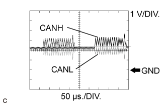
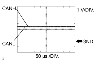
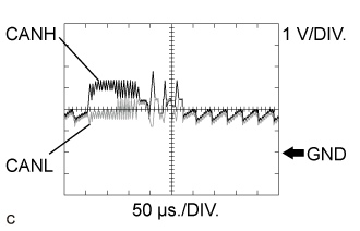
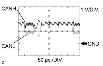
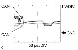
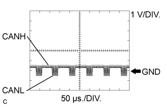
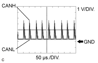
| CAN BUS WAVEFORMS |

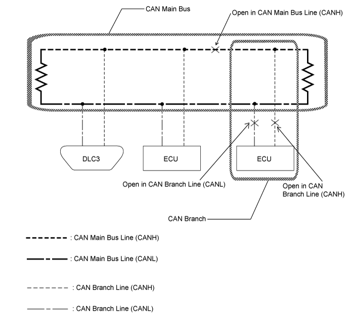
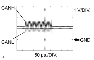
CAN bus waveforms (Group 1)
![]() |
Normal waveform
![]() |
Open in both of the lines (CANH and CANL) of a CAN branch
![]() |
Short between the CAN bus lines (CANH and CANL)
CAN bus waveforms (reference) (Group 2)
![]() |
Open in a CAN branch line (CANH)
![]() |
Open in a CAN branch line (CANL)
![]() |
Open in a CAN main bus line (CANH)
![]() |
Short between a CAN bus line (CANH) and ground
![]() |
Short between a CAN bus line (CANL) and ground
| DATA SENDING/RECEIVING TABLE |
Data sending/receiving table
| Data content | Data Detected and Sent by | Data Received by (Can be Checked in the Data List) | Data Received by (Cannot be Checked in the Data List) | Relevant Data List Item [Selected System] |
| Accelerator position | Hybrid vehicle control computer assembly (HV CPU) | - | Combination meter assembly | Accelerator Degree [Hybrid Control] |
| Engine speed | ECM | - |
| Engine Speed [Engine and ECT] |
| Engine coolant temperature | ECM |
| - |
|
| Vehicle speed | Brake booster with master cylinder assembly (Skid control ECU) |
| Airbag sensor assembly |
|
| Combination meter assembly*3 | - |
| Vehicle Speed Meter [Combination Meter] | |
| Shift position | Hybrid vehicle control computer assembly (HV CPU) | - |
| Shift Sensor Shift Pos [Hybrid Control] |
| Ambient temperature | Air conditioning amplifier assembly |
| Main body ECU (Multiplex network body ECU) |
|
| Driver door courtesy | Main body ECU (Multiplex network body ECU) | - |
| FL Door Courtesy [Main Body] |
| Steering angle sensor | Spiral cable with sensor sub-assembly (Steering sensor) | Brake booster with master cylinder assembly (Skid control ECU) |
| Steering Angle Sensor [ABS/VSC/TRC] |
| Yaw rate sensor | Airbag sensor assembly (built-in type yaw rate sensor) | Brake booster with master cylinder assembly (Skid control ECU) | Power steering ECU assembly |
|
| Deceleration sensor | Airbag sensor assembly (built-in type yaw rate sensor) | Brake booster with master cylinder assembly (Skid control ECU) |
|
|
| Hybrid vehicle control computer assembly (HV CPU) power source voltage | Hybrid vehicle control computer assembly (HV CPU)*1 | - | - | +B [Hybrid Control] |
| Smart key ECU assembly (Certification ECU) (Power Management CPU) power source state | Smart key ECU assembly (Certification ECU) (Power management CPU)*1 | - | - | Power Supply Condition [Power Source Control] |
| ECM power source voltage | ECM*1 | - | - | Battery Voltage [Engine and ECT] |
| Brake pedal stroke sensor | Brake booster with master cylinder assembly (Skid control ECU)*1 | - | - |
|
| Power steering ECU assembly power source voltage | Power steering ECU assembly*1 | - | - | IG Power Supply [EMPS] |
| Intensity of light received by the solar sensor | Air conditioning amplifier assembly*1 | - | - | Solar Sensor (D Side) [Air Conditioner] |
| Combination meter assembly power source voltage | Combination meter assembly*1 | - | - | +B Voltage Value [Combination Meter] |
| Driver door touch sensor | Smart key ECU assembly (Certification ECU)*1 | - | - | D-Door Touch Sensor [Entry&Start] |
Details of relevant Data List items (Selected system: Hybrid Control)
Connect the GTS to the DLC3.
Turn the power switch on (IG).
Enter the following menus: Powertrain / Hybrid Control / Data List.
Check the results by referring to the following table.
| Tester Display | Measurement Item/Range | Normal Condition | Diagnostic Note |
| Vehicle Spd | Vehicle speed/ Min.: 0 km/h (0 mph), Max.: 255 km/h (158 mph) | Vehicle stopped: 0 km/h (0 mph) While driving at a constant speed: No significant fluctuation | - |
| +B | Auxiliary battery voltage/ Min.: 0.00 V, Max.: 65.53 V | Constant: 10.00 to 15.00 V | Auxiliary battery condition |
| Accelerator Degree | Accelerator pedal depressed angle/ Min.: 0.0%, Max.: 100.0% | Accelerator pedal depressed: Changes with accelerator pedal pressure | Accelerator pedal sensor assembly |
| Ambient Temperature | Ambient air temperature/ Min.: -40°C (-40°F), Max.: 215°C (419°F) | Power switch on (IG): Same as ambient air temperature | Ambient temperature sensor |
| Shift Sensor Shift Pos | Shift position/ P/R/N/D/B | Matches currently selected shift position: P, R, N, D or B | Shift lever position sensor |
Details of relevant Data List items (Selected system: Power Source Control)
Connect the GTS to the DLC3.
Turn the power switch on (IG).
Turn the GTS on.
Enter the following menus: Body / Power Source Control / Data List.
Check the results by referring to the following table.
| Tester Display | Measurement Item/Range | Normal Condition | Diagnostic Note |
| Power Supply Condition | Power supply state/IG2 ON, ST ON, All OFF, IG1 ON or ACC ON | All OFF: Power switch off ACC ON: Power switch on (ACC) IG1 ON: Power switch on (IG) (IG1 relay on) IG2 ON: Power switch on (IG) (IG2 relay on) ST ON: Sending hybrid control system start request signal | Since the IG1 and IG2 relays turn on at approximately the same time, IG1 ON may not be displayed (the IG1 relay turns on for a very short time). |
Details of relevant Data List items (Selected system: Engine and ECT)
Connect the GTS to the DLC3.
Turn the power switch on (IG).
Turn the tester on.
Put the engine in inspection mode (maintenance mode) (Click here).
Warm up the engine.
Turn the A/C switch off.
Turn the power switch off.
Turn the power switch on (IG).
Turn the tester on.
Enter the following menus: Powertrain / Engine and ECT / Data List.
According to the display on the GTS, read the Data List.
| Tester Display | Measurement Item/Range | Normal Condition | Diagnostic Note |
| Engine Speed | Engine speed/ Min.: 0 rpm, Max.: 16383 rpm | 950 to 1050 rpm: Idling | When the crank position sensor is malfunctioning, "Engine Speed" is approximately 0 rpm or varies greatly from the actual engine speed. |
| Coolant Temp | Coolant temperature/ Min.: -40°C (-40°F), Max.: 140°C (284°F) | 75 to 100°C (167 to 212°F): After warming up | This is the engine coolant temperature.
|
| Battery Voltage | Auxiliary battery voltage/ Min.: 0 V, Max.: 65.535 V | 11 to 16 V: Power switch on (IG) | If 11 V or less, characteristics of some electrical components may change. |
| Ambient Temp for A/C | Ambient temperature for A/C/ Min.: -40°C (-40°F), Max.: 215°C (419°F) | - | - |
Details of relevant Data List items (Selected system: ABS/VSC/TRC)
Warm up the engine.
Turn the power switch off.
Connect the GTS to the DLC3.
Turn the power switch on (IG).
Turn the GTS on.
Enter the following menus: Chassis / ABS/VSC/TRC / Data List.
According to the display on the GTS, read the Data List.
| Tester Display | Measurement Item/Range | Normal Condition | Diagnostic Note |
| Stroke Sensor | Brake pedal stroke sensor assembly / Min.: 0.00 V, Max.: 5.00 V | When brake pedal released: 0.65 to 1.35 V | Reading increases when brake pedal is depressed |
| Stroke Sensor2 | Brake pedal stroke sensor assembly 2 / Min.: 0.00 V, Max.: 5.00 V | When brake pedal released: 3.65 to 4.35 V | Reading decreases when brake pedal is depressed |
| Deceleration Sensor | Acceleration sensor 1 / Min.: -18.525 m/s2, Max.: 18.387 m/s2
| - | During deceleration/acceleration: Changes continuously |
| Deceleration Sensor2 | Acceleration sensor 2 / Min.: -18.525 m/s2, Max.: 18.387 m/s2
| - | During deceleration/acceleration: Changes continuously |
| Yaw Rate Sensor | Yaw rate sensor 1 / Min.: -128°/s, Max.: 127°/s | Vehicle stationary: 0°/s Turning right: -128 to 0°/s Turning left: 0 to 127°/s | - |
| Yaw Rate Sensor2 | Yaw rate sensor 2 / Min.: -128°/s, Max.: 127°/s | Vehicle stationary: 0°/s Turning right: -128 to 0°/s Turning left: 0 to 127°/s | - |
| Steering Angle Sensor | Steering angle sensor / Min.: -3276.8°, Max.: 3276.7° | Turning left: Increases Turning right: Decreases | - |
| Vehicle Speed | Maximum wheel speed sensor / Min.: 0 km/h (0 mph), Max.: 326 km/h (202 mph) | Vehicle stopped: 0 km/h (0 mph) | When driving at constant speed: No large fluctuations |
Details of relevant Data List items (Selected system: EMPS)
Turn the power switch off.
Connect the GTS to the DLC3.
Turn the power switch on (IG).
Turn the GTS on.
Enter the following menus: Chassis / EMPS / Data List.
According to the display on the GTS, read the Data List.
| Tester Display | Measurement Item/Range | Normal Condition | Diagnostic Note |
| Meter Vehicle Velocity | Vehicle speed from meter/ Min.: 0 km/h (0 mph) Max.: 300.0 km/h (186.4 mph) | 0 km/h (0 mph) | Power switch on (READY) and vehicle stopped |
| No significant fluctuation | Power switch on (READY) and vehicle driven at a constant speed | ||
| IG Power Supply | ECU power source voltage/ Min.: 0.0000 V Max.: 20.1531 V | 9 to 16 V | Power switch on (IG) |
Details of relevant Data List items (Selected system: Entry&Start)
Connect the GTS to the DLC3.
Turn the power switch on (IG).
Turn the GTS on.
Enter the following menus: Body / Entry&Start / Data List.
Read the Data List according to the display on the GTS.
| Tester Display | Measurement Item/Range | Normal Condition | Diagnostic Note |
| D-Door Touch Sensor | Driver door touch sensor (unlock sensor) / ON or OFF | ON: Driver door touch sensor (unlock sensor) touched OFF: Driver door touch sensor (unlock sensor) not touched |
|
Details of relevant Data List items (Selected system: Combination Meter)
Warm up the engine.
Turn the power switch off.
Connect the GTS to the DLC3.
Turn the power switch on (IG).
Turn the GTS on.
Enter the following menus: Body / Combination Meter / Data List.
| Tester Display | Measurement Item/Range | Normal Condition | Diagnostic Note |
| Vehicle Speed Meter | Vehicle speed/Min.: 0 km/h (0 mph), Max.: 255 km/h (158 mph) | Almost the same as actual vehicle speed | - |
| Coolant Temperature | Engine coolant temperature/-40 to 127.5°C (-40 to 261.5°F) | After warming up: 75 to 100°C (167 to 212°F) |
|
| +B Voltage Value | Auxiliary battery voltage/Min.: 0 V, Max.: 25.5 V | 11 to 16 V | - |
| Ambient Temperature | Outside temperature/Min.: -40°C (-40°F), Max.: 87.5°C (189.5°F) | Almost the same as actual outside temperature | The temperature displayed on the multi-information display is -40 to 50°C (-40 to 122°F) |
Details of relevant Data List items (Selected system: Air Conditioner)
Connect the GTS to the DLC3.
Turn the power switch on (IG).
Turn the GTS on.
Enter the following menus: Body / Air Conditioner / Data List.
Check the value(s) by referring to the table below.
| Tester Display | Measurement Item/Range | Normal Condition | Diagnostic Note |
| Ambient Temp Sensor | Ambient temperature sensor (thermistor assembly) / Min.: -23.30°C (-9.94°F) Max.: 65.95°C (150.71°F) | Actual ambient temperature displayed | - |
| Solar Sensor (D Side) | Solar sensor / Min.: 0 Max.: 255 | Solar sensor value increases as brightness increases | - |
| Engine Coolant Temp | Engine coolant temperature sensor / Min.: 1.30°C (34.34°F) Max.: 90.55°C (194.99°F) | Actual engine coolant temperature displayed | - |
Details of relevant Data List items (Selected system: Main Body ECU)
Connect the GTS to the DLC3.
Turn the power switch on (IG).
Turn the GTS on.
Enter the following menus: Body / Main Body / Data List.
Read the Data List according to the display on the GTS.
| Tester Display | Measurement Item/Range | Normal Condition | Diagnostic Note |
| FL Door Courtesy | Front door courtesy light switch LH signal/CLOSE or OPEN | CLOSE: Front door LH closed OPEN: Front door LH open | - |