RM3210E
_56
Audio / Visual / Telematics
_047512
PARK ASSIST / MONITORING
_0229674
REAR VIEW MONITOR SYSTEM
J
PARK ASSIST / MONITORING REAR VIEW MONITOR SYSTEM Image from Camera for Rear View Monitor is Abnormal
DESCRIPTION
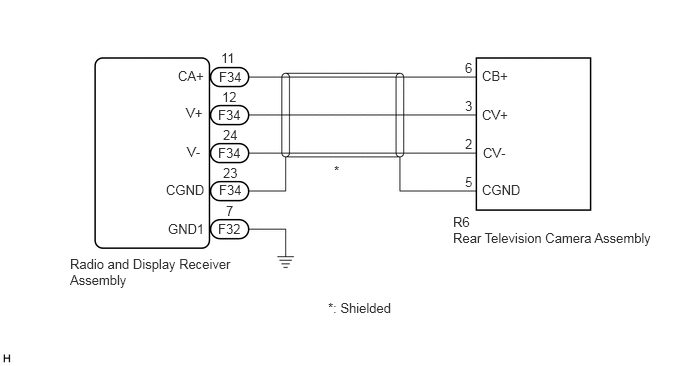
The video signal of the rear television camera assembly is transmitted to the radio and display receiver assembly.
WIRING DIAGRAM
2.302,0.521 2.625,0.729
0.323,0.208
10
false
11
2.271,1.115 2.729,1.313
0.458,0.198
10
false
F34
2.271,1.51 2.729,1.708
0.458,0.198
10
false
F34
2.281,1.896 2.74,2.094
0.458,0.198
10
false
F34
2.271,2.302 2.542,2.51
0.271,0.208
10
false
F32
1.854,0.708 2.313,0.906
0.458,0.198
10
false
CA+
1.938,1.094 2.396,1.292
0.458,0.198
10
false
V+
1.948,1.5 2.406,1.698
0.458,0.198
10
false
V-
1.729,1.896 2.25,2.115
0.521,0.219
10
false
CGND
1.75,2.302 2.271,2.521
0.521,0.219
10
false
GND1
2.313,0.927 2.635,1.135
0.323,0.208
10
false
12
2.323,1.323 2.646,1.531
0.323,0.208
10
false
24
2.323,1.719 2.646,1.927
0.323,0.208
10
false
23
2.281,0.719 2.74,0.917
0.458,0.198
10
false
F34
2.354,2.115 2.677,2.323
0.323,0.208
10
false
7
4.844,0.625 5.167,0.833
0.323,0.208
10
false
6
4.844,1.021 5.167,1.229
0.323,0.208
10
false
3
4.844,1.417 5.146,1.635
0.302,0.219
10
false
2
4.844,1.813 5.167,2.021
0.323,0.208
10
false
5
5.021,0.708 5.479,0.906
0.458,0.198
10
false
CB+
5.021,1.115 5.479,1.313
0.458,0.198
10
false
CV+
5.031,1.51 5.5,1.75
0.469,0.24
10
false
CV-
5.021,1.896 5.542,2.115
0.521,0.219
10
false
CGND
4.719,2.229 5.177,2.427
0.458,0.198
10
false
R6
4.719,2.396 6.969,2.625
2.25,0.229
10
false
Rear Television Camera Assembly
3.479,1.698 3.646,1.844
0.167,0.146
10
false
*
0.729,2.667 2.427,3
1.698,0.333
10
false
Radio and Display Receiver Assembly
3.417,3.125 4.542,3.354
1.125,0.229
10
false
*: Shielded
PROCEDURE
1.CHECK HARNESS AND CONNECTOR (RADIO AND DISPLAY RECEIVER ASSEMBLY - REAR TELEVISION CAMERA ASSEMBLY)
Click hereAudio / Visual / Telematics>PARK ASSIST / MONITORING>REAR VIEW MONITOR SYSTEM>C1622
- Result:
Proceed to OK NG
OK
2.INSPECT RADIO AND DISPLAY RECEIVER ASSEMBLY
NG
REPAIR OR REPLACE HARNESS OR CONNECTOR
2.INSPECT RADIO AND DISPLAY RECEIVER ASSEMBLY
Click hereAudio / Visual / Telematics>PARK ASSIST / MONITORING>REAR VIEW MONITOR SYSTEM>C1622
- Result:
Proceed to OK NG
OK
3.INSPECT REAR TELEVISION CAMERA ASSEMBLY
NG
REPLACE RADIO AND DISPLAY RECEIVER ASSEMBLY
3.INSPECT REAR TELEVISION CAMERA ASSEMBLY
Click hereAudio / Visual / Telematics>PARK ASSIST / MONITORING>REAR VIEW MONITOR SYSTEM>C1622
- Result:
Proceed to OK NG
OK
PROCEED TO NEXT SUSPECTED AREA SHOWN IN PROBLEM SYMPTOMS TABLE
Click hereAudio / Visual / Telematics>PARK ASSIST / MONITORING>REAR VIEW MONITOR SYSTEM>PROBLEM SYMPTOMS TABLE
NG
REPLACE REAR TELEVISION CAMERA ASSEMBLY