METER / GAUGE / DISPLAY COMBINATION METER INSTALLATION
PROCEDURE

 1.INSTALL COMBINATION METER ASSEMBLY
Connect the 2 connectors.
Engage the clamp.
Install the combination meter assembly with the 4 screws.
55410C
2.INSTALL INSTRUMENT CLUSTER FINISH PANEL ASSEMBLY
Engage the 10 guides and 17 clips to install the instrument cluster finish panel assembly as shown in the illustration.
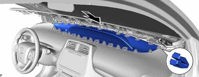

|
Install in this Direction | - | - |
Engage the 4 guides and 11 clips to install the upper instrument panel assembly as shown in the illustration.
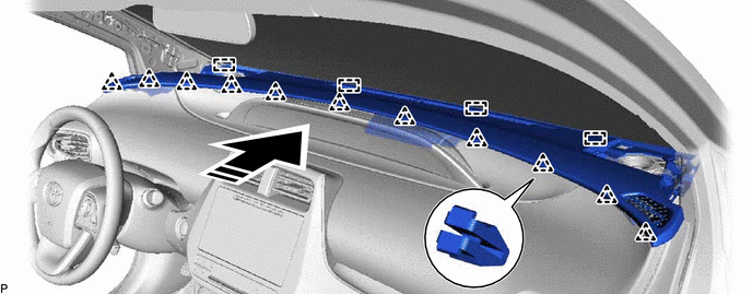
|
|
Install in this Direction | - | - |
- NOTICE:
- ·
Do not damage the upper instrument panel assembly.
·Do not allow the wire harnesses to interfere with the surrounding parts.
Install the 2 clips.
55409F
3.INSTALL NO. 2 INSTRUMENT PANEL SPEAKER PANEL SUB-ASSEMBLY
62211
4.INSTALL FRONT PILLAR GARNISH RH
- HINT:
-
Use the same procedure as for the LH side.
-
Click hereVehicle Interior>INTERIOR PANELS / TRIM>ROOF HEADLINING>INSTALLATION
62311B
5.INSTALL FRONT DOOR OPENING TRIM WEATHERSTRIP RH
55408F
6.INSTALL NO. 1 INSTRUMENT PANEL SPEAKER PANEL SUB-ASSEMBLY
62212
7.INSTALL FRONT PILLAR GARNISH LH
62312B
8.INSTALL FRONT DOOR OPENING TRIM WEATHERSTRIP LH
9.CONNECT CABLE TO NEGATIVE AUXILIARY BATTERY TERMINAL
- NOTICE:
-
When disconnecting the cable, some systems need to be initialized after the cable is reconnected.
-
Click hereGeneral>INTRODUCTION>REPAIR INSTRUCTION>INITIALIZATION