2ZR-FXE COOLING EXHAUST PIPE GAS CONTROL ACTUATOR INSTALLATION
PROCEDURE

 17495
1.INSTALL EXHAUST PIPE GAS CONTROL ACTUATOR
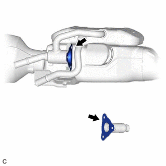
Clean the installation surfaces and bolt holes of the exhaust pipe gas control actuator sub-assembly and front exhaust pipe assembly (TWC: Rear Catalyst).
- NOTICE:
-
Make sure no foreign matter enters to the exhaust pipe gas control actuator sub-assembly and front exhaust pipe assembly (TWC: Rear Catalyst).
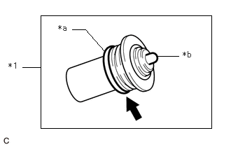
| *1 | Exhaust Pipe Gas Control Actuator |
| *a | O-ring |
| *b | Piston |
Apply clean engine coolant to the O-ring.
- NOTICE:
-
Check that the O-ring is not deformed, cracked or swollen.
Install the exhaust pipe gas control actuator.
- NOTICE:
- ·
When installing the exhaust pipe gas control actuator, do not push on the piston.
·Make sure that the exhaust pipe gas control actuator is free of oil.
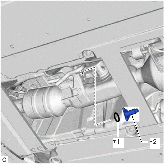
| *1 | Exhaust Pipe Gas Control Actuator Gasket |
| *2 | Exhaust Pipe Gas Control Actuator Sub-assembly |
Install a new exhaust pipe gas control actuator gasket and the exhaust pipe gas control actuator sub-assembly with the 3 bolts.
- Torque:
- 5.0 N*m (51 kgf*cm, 44 in.*lbf)
- NOTICE:
- ·
Check that the O-ring is not deformed, cracked or swollen.
·Make sure that the exhaust pipe gas control actuator gasket and exhaust pipe gas control actuator sub-assembly are free of oil.
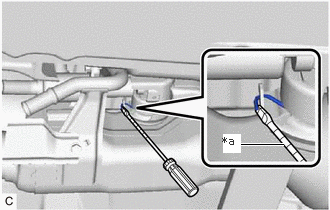
| *a | Protective Tape |
Using a screwdriver with the tip taped, pry the portion indicated in the illustration to engage the spring.
Connect the outlet heater water hose B and outlet heater water hose C to the No. 2 outlet water pipe and inlet water pipe and slide the 2 clips to secure them.
- NOTICE:
-
When installing the outlet heater water hose B and outlet heater water hose C, ensure that the exhaust heat recirculation system is filled with coolant. Otherwise, the engine water pump assembly may be damaged.
2.ADD ENGINE COOLANT (for Engine)
3.INSPECT FOR COOLANT LEAK (for Engine)
51444C
4.INSTALL REAR MOTOR UNDER COVER LH