Home › Vehicle Interior › HEATING / AIR CONDITIONING › AIR CONDITIONING SYSTEM
RM3210E _58 Vehicle Interior _047534 HEATING / AIR CONDITIONING _0244634 AIR CONDITIONING SYSTEM J

HEATING / AIR CONDITIONING  AIR CONDITIONING SYSTEM  PTC Heater Circuit  


DESCRIPTION

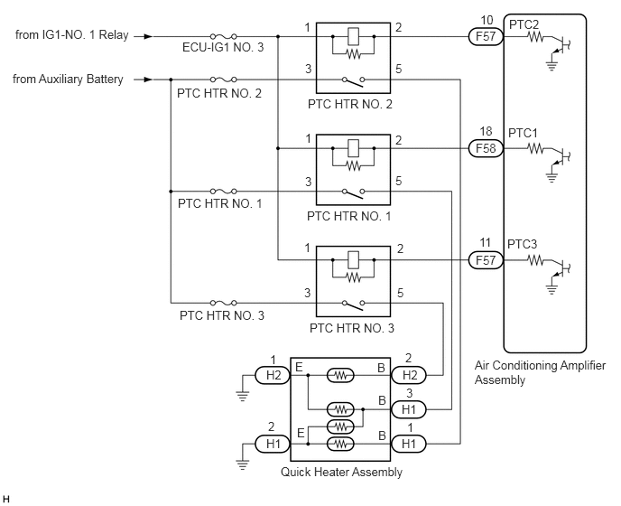
The air conditioning amplifier assembly sends operation signals to the PTC heater relays when quick heater assembly operation conditions are met. Based on the signals from the air conditioning amplifier assembly, the PTC heater relays turn on, and power is supplied to the quick heater assembly installed in the air conditioning radiator assembly.

Quick Heater Assembly Operation Condition
Control ECU Condition
Air Conditioning Amplifier Assembly Power switch on (READY)
ECO mode: Off
Blower switch: On
Temperature setting: MAX HOT
Light control switch off
·

Engine coolant temperature 65°C (149°F) or lower (3 PTC heater relays operating)

·

Engine coolant temperature 70°C (158°F) or lower (2 PTC heater relays operating)

·

Engine coolant temperature 75°C (167°F) or lower (1 PTC heater relay operating)


·

Ambient temperature -7°C (19°F) or lower (3 PTC heater relays operating)

·

Ambient temperature 16°C (61°F) or lower (2 PTC heater relays operating)

·

Ambient temperature 25°C (77°F) or lower (1 PTC heater relay operating)


WIRING DIAGRAM

E338822E01
5.542,0.146 5.854,0.344 0.313,0.198 10 false 10 0.177,0.313 1.875,0.552 1.698,0.24 10 false from IG1-NO. 1 Relay 0.146,0.823 1.844,1.063 1.698,0.24 10 false from Auxiliary Battery 3.51,0.229 3.823,0.427 0.313,0.198 10 false 1 4.563,0.229 4.875,0.427 0.313,0.198 10 false 2 3.521,0.708 3.833,0.906 0.313,0.198 10 false 3 4.563,0.708 4.875,0.906 0.313,0.198 10 false 5 3.521,1.51 3.833,1.708 0.313,0.198 10 false 1 4.563,1.531 4.875,1.729 0.313,0.198 10 false 2 4.563,2 4.875,2.198 0.313,0.198 10 false 5 3.521,2.01 3.833,2.208 0.313,0.198 10 false 3 3.51,2.771 3.823,2.969 0.313,0.198 10 false 1 4.583,2.781 4.896,2.979 0.313,0.198 10 false 2 3.51,3.292 3.823,3.49 0.313,0.198 10 false 3 4.583,3.292 4.896,3.49 0.313,0.198 10 false 5 5.49,0.333 5.802,0.531 0.313,0.198 10 false F57 5.49,1.625 5.802,1.823 0.313,0.198 10 false F58 5.49,2.917 5.802,3.115 0.313,0.198 10 false F57 5.531,1.427 5.844,1.625 0.313,0.198 10 false 18 5.531,2.708 5.844,2.906 0.313,0.198 10 false 11 5.854,2.729 6.313,2.927 0.458,0.198 10 false PTC3 5.865,1.448 6.323,1.646 0.458,0.198 10 false PTC1 5.875,0.198 6.333,0.396 0.458,0.198 10 false PTC2 3.552,1.115 4.708,1.302 1.156,0.188 10 false PTC HTR NO. 2 3.542,2.406 4.698,2.594 1.156,0.188 10 false PTC HTR NO. 1 3.573,3.698 4.729,3.885 1.156,0.188 10 false PTC HTR NO. 3 3.073,4.24 3.385,4.438 0.313,0.198 10 false H2 3.073,5.031 3.385,5.229 0.313,0.198 10 false H1 4.646,4.24 4.958,4.438 0.313,0.198 10 false H2 4.635,4.635 4.948,4.833 0.313,0.198 10 false H1 4.635,5.031 4.948,5.229 0.313,0.198 10 false H1 4.677,4.042 4.99,4.24 0.313,0.198 10 false 2 4.688,4.448 5,4.646 0.313,0.198 10 false 3 4.698,4.844 5.01,5.042 0.313,0.198 10 false 1 3.115,4.063 3.427,4.26 0.313,0.198 10 false 1 3.094,4.833 3.406,5.031 0.313,0.198 10 false 2 3.406,4.146 3.719,4.344 0.313,0.198 10 false E 3.427,4.906 3.74,5.104 0.313,0.198 10 false E 4.354,4.156 4.667,4.354 0.313,0.198 10 false B 4.365,4.531 4.677,4.729 0.313,0.198 10 false B 4.365,4.938 4.677,5.135 0.313,0.198 10 false B 3.24,5.354 5.01,5.542 1.771,0.188 10 false Quick Heater Assembly 5.479,4.125 7.083,4.604 1.604,0.479 10 false Air Conditioning Amplifier Assembly 2.052,2.26 3.208,2.448 1.156,0.188 10 false PTC HTR NO. 1 2.042,0.99 3.198,1.177 1.156,0.188 10 false PTC HTR NO. 2 2.073,3.552 3.229,3.74 1.156,0.188 10 false PTC HTR NO. 3 2.104,0.458 3.802,0.698 1.698,0.24 10 false ECU-IG1 NO. 3

CAUTION / NOTICE / HINT

NOTICE:

Inspect the fuses for circuits related to this system before performing the following procedure.


PROCEDURE

1.PERFORM ACTIVE TEST USING GTS
a.

Connect the GTS to the DLC3.


b.

Turn the power switch on (IG).


c.

Turn the GTS on.


d.

Enter the following menus: Body Electrical / Air Conditioner / Active Test.


e.

Perform the Active Test according to the display on the GTS.

Body Electrical > Air Conditioner > Active Test
Tester Display Measurement Item Control Range Diagnostic Note
Heater Active Level Quick heater assembly Min.: 0, Max.: 3 -
Body Electrical > Air Conditioner > Active Test
Tester Display
Heater Active Level
50004 121 33
OK:

Heater Active Level changes normally.


Result:
Proceed to
OK
NG


OK

2.INSPECT PTC HEATER RELAY

NG

PROCEED TO NEXT SUSPECTED AREA SHOWN IN PROBLEM SYMPTOMS TABLE

2.INSPECT PTC HEATER RELAY
a.

Remove the PTC heater relays.


b.

Measure the resistance according to the value(s) in the table below.
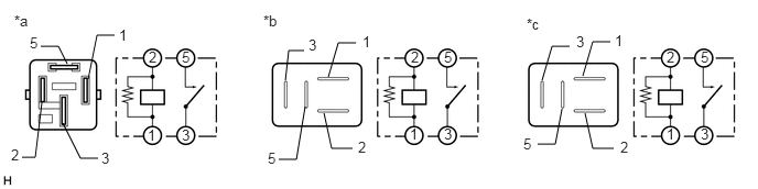
E338823C01
0.385,0.438 0.552,0.438 0.552,0.438 0.635,0.604 false 1.083,0.333 0.917,0.333 0.917,0.333 0.833,0.75 false 0.927,1.5 0.76,1.5 0.76,1.5 0.594,1.167 false 0.208,1.49 0.333,1.49 0.333,1.49 0.396,0.969 false 3.365,0.406 3.198,0.406 3.198,0.406 3.104,0.729 false 2.875,0.479 2.729,0.479 2.729,0.479 2.698,0.76 false 2.635,1.51 2.802,1.51 2.802,1.51 2.885,1.01 false 3.333,1.406 3.135,1.406 3.135,1.406 3.063,1.073 false 5.385,0.438 5.219,0.438 5.219,0.438 5.125,0.76 false 5.771,0.396 5.604,0.396 5.604,0.396 5.51,0.719 false 5.802,1.406 5.604,1.406 5.604,1.406 5.531,1.073 false 5.083,1.365 5.25,1.365 5.25,1.365 5.313,1.031 false 0.135,0.115 0.448,0.271 0.313,0.156 10 false *a 2.49,0.115 2.802,0.271 0.313,0.156 10 false *b 4.979,0.146 5.292,0.302 0.313,0.156 10 false *c 1.719,1.198 1.927,1.417 0.208,0.219 10 false 3 4.198,1.188 4.406,1.406 0.208,0.219 10 false 3 6.625,1.188 6.833,1.406 0.208,0.219 10 false 3 1.719,0.458 1.927,0.677 0.208,0.219 10 false 5 4.198,0.458 4.406,0.677 0.208,0.219 10 false 5 6.625,0.458 6.833,0.677 0.208,0.219 10 false 5 1.396,1.198 1.604,1.417 0.208,0.219 10 false 1 1.406,0.458 1.615,0.677 0.208,0.219 10 false 2 3.885,0.458 4.094,0.677 0.208,0.219 10 false 2 3.875,1.188 4.083,1.406 0.208,0.219 10 false 1 6.302,1.188 6.51,1.406 0.208,0.219 10 false 1 6.302,0.458 6.51,0.677 0.208,0.219 10 false 2 1.125,0.25 1.333,0.469 0.208,0.219 10 false 1 0.281,0.323 0.49,0.542 0.208,0.219 10 false 5 0.104,1.385 0.313,1.604 0.208,0.219 10 false 2 0.958,1.417 1.167,1.635 0.208,0.219 10 false 3 3.427,0.313 3.635,0.531 0.208,0.219 10 false 1 3.385,1.313 3.594,1.531 0.208,0.219 10 false 2 2.917,0.344 3.125,0.563 0.208,0.219 10 false 3 2.531,1.417 2.74,1.635 0.208,0.219 10 false 5 5.813,0.302 6.021,0.521 0.208,0.219 10 false 1 5.865,1.313 6.073,1.531 0.208,0.219 10 false 2 5.448,0.313 5.656,0.531 0.208,0.219 10 false 3 4.948,1.281 5.156,1.5 0.208,0.219 10 false 5
*a Component without harness connected
(PTC HTR NO. 1)
*b Component without harness connected
(PTC HTR NO. 2)
*c Component without harness connected
(PTC HTR NO. 3)
- -


Standard Resistance:
Tester Connection Condition Specified Condition
3 - 5 Auxiliary battery voltage not applied between terminals 1 and 2 10 kΩ or higher
3 - 5 Auxiliary battery voltage applied between terminals 1 and 2 Below 1 Ω


Result:
Proceed to
OK
NG


OK

3.CHECK HARNESS AND CONNECTOR (PTC HEATER RELAY - POWER SOURCE)

NG

3.CHECK HARNESS AND CONNECTOR (PTC HEATER RELAY - POWER SOURCE)
a.

Measure the voltage according to the value(s) in the table below.

Standard Voltage:
PTC HTR NO. 1:
Tester Connection Condition Specified Condition
Relay terminal 3 - Body ground Power switch off 11 to 14 V
Relay terminal 1 - Body ground Power switch off Below 1 V
Relay terminal 1 - Body ground Power switch on (IG) 11 to 14 V


Standard Voltage:
PTC HTR NO. 2:
Tester Connection Condition Specified Condition
Relay terminal 3 - Body ground Power switch off 11 to 14 V
Relay terminal 1 - Body ground Power switch off Below 1 V
Relay terminal 1 - Body ground Power switch on (IG) 11 to 14 V


Standard Voltage:
PTC HTR NO. 3:
Tester Connection Condition Specified Condition
Relay terminal 3 - Body ground Power switch off 11 to 14 V
Relay terminal 1 - Body ground Power switch off Below 1 V
Relay terminal 1 - Body ground Power switch on (IG) 11 to 14 V


Result:
Proceed to
OK
NG


OK

4.CHECK HARNESS AND CONNECTOR (PTC HEATER RELAY - AIR CONDITIONING AMPLIFIER ASSEMBLY)

NG

REPAIR OR REPLACE HARNESS OR CONNECTOR

4.CHECK HARNESS AND CONNECTOR (PTC HEATER RELAY - AIR CONDITIONING AMPLIFIER ASSEMBLY)
a.

Disconnect the F57 and F58 air conditioning amplifier assembly connectors.


b.

Measure the resistance according to the value(s) in the table below.

Standard Resistance:
PTC HTR NO. 1:
Tester Connection Condition Specified Condition
Relay terminal 2 - F58-18 (PTC1) Always Below 1 Ω
Relay terminal 2 or F58-18 (PTC1) - Body ground Always 10 kΩ or higher


Standard Resistance:
PTC HTR NO. 2:
Tester Connection Condition Specified Condition
Relay terminal 2 - F57-10 (PTC2) Always Below 1 Ω
Relay terminal 2 or F57-10 (PTC2) - Body ground Always 10 kΩ or higher


Standard Resistance:
PTC HTR NO. 3:
Tester Connection Condition Specified Condition
Relay terminal 2 - F57-11 (PTC3) Always Below 1 Ω
Relay terminal 2 or F57-11 (PTC3) - Body ground Always 10 kΩ or higher


Result:
Proceed to
OK
NG


OK

5.CHECK HARNESS AND CONNECTOR (PTC HEATER RELAY - QUICK HEATER ASSEMBLY AND BODY GROUND)

NG

REPAIR OR REPLACE HARNESS OR CONNECTOR

5.CHECK HARNESS AND CONNECTOR (PTC HEATER RELAY - QUICK HEATER ASSEMBLY AND BODY GROUND)
a.

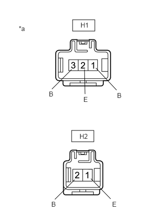
Disconnect the H1 and H2 quick heater assembly connectors.


b.

Measure the resistance according to the value(s) in the table below.

Standard Resistance:
PTC HTR NO. 1:
Tester Connection Condition Specified Condition
Relay terminal 5 - H1-3 (B) Always Below 1 Ω
H1-2 (E) - Body ground Always Below 1 Ω
H2-1 (E) - Body ground Always Below 1 Ω
H1-3 (B) - Body ground Always 10 kΩ or higher


Standard Resistance:
PTC HTR NO. 2:
Tester Connection Condition Specified Condition
Relay terminal 5 - H1-1 (B) Always Below 1 Ω
H1-2 (E) - Body ground Always Below 1 Ω
H1-1 (B) - Body ground Always 10 kΩ or higher


Standard Resistance:
PTC HTR NO. 3:
Tester Connection Condition Specified Condition
Relay terminal 5 - H2-2 (B) Always Below 1 Ω
H2-1 (E) - Body ground Always Below 1 Ω
H2-2 (B) - Body ground Always 10 kΩ or higher


Result:
Proceed to
OK
NG


OK

6.INSPECT QUICK HEATER ASSEMBLY

NG

REPAIR OR REPLACE HARNESS OR CONNECTOR

6.INSPECT QUICK HEATER ASSEMBLY
a.

b.
E170870C27
1.531,0.417 2,0.656 0.469,0.24 1.51,2.76 1.979,3 0.469,0.24 1.094,1.885 1.51,1.469 false 2.458,1.906 2.021,1.438 false 1.792,1.99 1.781,1.469 false 1.156,4.219 1.573,3.802 false 2.333,4.208 1.917,3.781 false 0.396,0.521 0.781,0.906 0.385,0.385 10 false *a 1.698,0.448 2.083,0.74 0.385,0.292 10 false H1 1.677,2.802 2.063,3.094 0.385,0.292 10 false H2 1.031,1.906 1.417,2.292 0.385,0.385 10 false B 1.76,2.021 2.146,2.406 0.385,0.385 10 false E 2.469,1.938 2.854,2.323 0.385,0.385 10 false B 1.083,4.24 1.469,4.625 0.385,0.385 10 false B 2.365,4.24 2.75,4.625 0.385,0.385 10 false E
*a Component without harness connected
(Quick Heater Assembly)


Measure the resistance according to the value(s) in the table below.

Standard Resistance:
Tester Connection Condition Specified Condition
H1-1 (B) - H1-2 (E) Always Below 1 Ω
H1-3 (B) - H1-2 (E) Always Below 1 Ω
H1-3 (B) - H2-1 (E) Always Below 1 Ω
H2-2 (B) - H2-1 (E) Always Below 1 Ω


Result:
Proceed to
OK
NG


OK

REPLACE AIR CONDITIONING AMPLIFIER ASSEMBLY

NG