2005-2008 RAV4 · Service Manual STEERING

INSTALLATION

Removal / installation · Vehicles built Jan 2007 – Jul 2007

Versions by build date: Nov 2005 – Dec 2006 Jan 2007 – Jul 2007 from Aug 2007


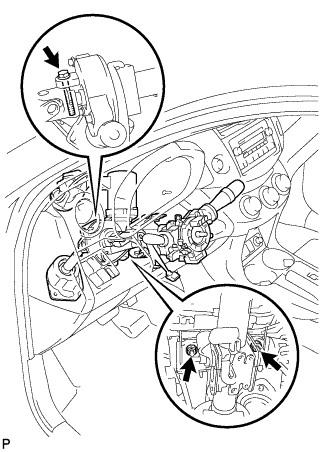
1. INSTALL STEERING COLUMN ASSEMBLY

C128489
  1. Install the steering column onto the instrument panel reinforcement with the 3 bolts.

    Torque:
    25 N*m{ 255 kgf*cm , 18 ft.*lbf }

  1. Connect all the connectors and clamp the wire harnesses onto the steering column bracket.


2. INSTALL BRAKE PEDAL SUPPORT ASSEMBLY
  1. Install the brake pedal support (Click here).


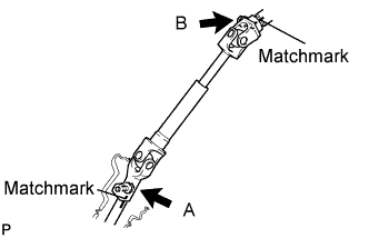
3. INSTALL STEERING INTERMEDIATE SHAFT ASSEMBLY NO.2

C128805E02
  1. Align the matchmarks on steering intermediate shaft and steering sliding yoke and temporarily install them with bolt B.

    Torque:
    35 N*m{ 360 kgf*cm , 26 ft.*lbf }

  1. Align the matchmarks on the steering sliding yoke and steering gear assembly and install them with bolt A.

    Torque:
    35 N*m{ 360 kgf*cm , 26 ft.*lbf }


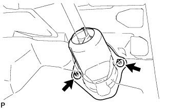
4. INSTALL COLUMN HOLE COVER SILENCER SHEET

C128486
  1. Install the column hole cover plate with the 2 clips.

  1. Install the floor carpet.


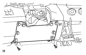
5. INSTALL LOWER INSTRUMENT PANEL FINISH PANEL (w/o Knee Airbag)

B132919
  1. Attach the 8 claws to install the lower instrument panel finish panel.

  1. Install the 2 screws.


6. INSTALL DRIVER SIDE KNEE AIRBAG ASSEMBLY (w/ Knee Airbag)

B127987
  1. Connect the connector.

    NOTICE:
    When handling the airbag connector, take care not to damage the airbag wire harness.

  1. Install the driver side knee airbag with the 4 bolts.

    Torque:
    10 N*m{ 101 kgf*cm , 7 ft.*lbf }


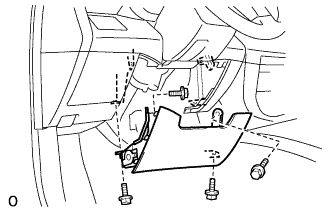
7. INSTALL NO. 1 INSTRUMENT PANEL UNDER COVER SUB-ASSEMBLY

B132919
  1. Attach the 8 claws to install the lower instrument panel finish panel.

  1. Install the 2 screws.


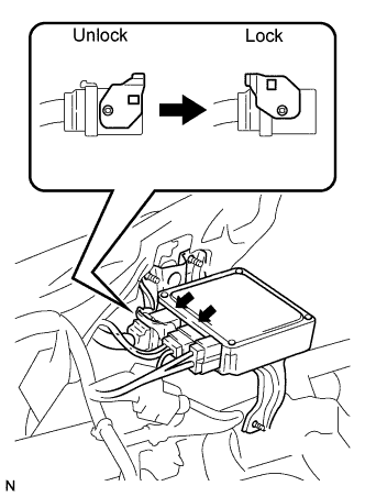
8. CONNECT POWER STEERING ECU

C128905E02
  1. Connect the 2 steering column connectors to the power steering ECU.

  1. Install the power steering motor wire harness and torque sensor wire harness clamps onto the side of the power steering ECU.

  1. Tilt the steering column up and down to make sure that the power steering motor wire harness and torque sensor wire harness do not interfere with any components.

9. INSTALL INSTRUMENT PANEL SUB-ASSEMBLY
  1. Install the instrument panel (Click here).


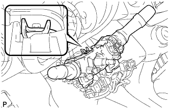
10. INSTALL COMBINATION SWITCH ASSEMBLY

C128800
  1. Install the turn signal switch onto the steering column with the clamp.


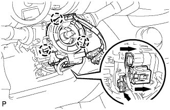
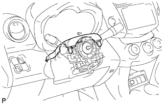
11. INSTALL SPIRAL CABLE SUB-ASSEMBLY
  1. Install the spiral cable onto the turn signal switch.

  1. C128493E03
    Connect all the connectors to the turn signal switch with spiral cable.


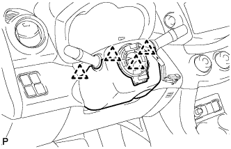
12. INSTALL STEERING COLUMN COVER

  1. C128492
    Attach the claw to install the upper steering column cover.

  1. C128491
    Attach the 4 claws to install the lower steering column cover.


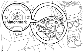
13. INSTALL STEERING WHEEL ASSEMBLY

  1. C132123E02
    Align the matchmarks and install the steering wheel onto the steering column.

  1. Install the nut.

    Torque:
    50 N*m{ 510 kgf*cm , 37 ft.*lbf }

  1. Connect all the connectors to the spiral cable.


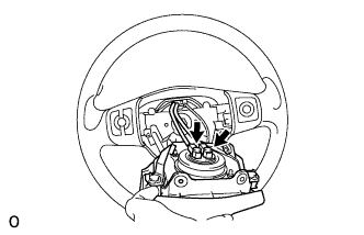
14. INSTALL STEERING PAD

B127893E01
  1. Support the steering pad with one hand as shown in the illustration.

  1. Connect the 2 airbag connectors.

    NOTICE:
    When handling the airbag connector, do not damage the airbag wire harness.

  1. Connect the horn connector.

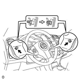
  1. Install the steering pad after confirming that the circumference grooves of the screws are caught on the screw case.

  1. B130245E02
    Using a T30 "torx" driver, install the 2 screws.

    Torque:
    8.8 N*m{ 90 kgf*cm , 78 in.*lbf }


15. POSITION FRONT WHEELS FACING STRAIGHT AHEAD

16. CONNECT CABLE TO NEGATIVE BATTERY TERMINAL

17. INSPECT SRS WARNING LIGHT
  1. Inspect the SRS warning light (Click here).

← INSTALLATION (Nov 2005 – Dec 2006)INSTALLATION (from Aug 2007) →