Power Source Mode does not Change
Circuit diagnosis · Vehicles built from Jan 2007
DESCRIPTION
When the certification ECU has detected the electrical key inside the cabin before the brake pedal is depressed, the power source mode can be changed in the following order sequentially by pressing the engine switch: off → on (ACC) → on (IG) → off.When one of the DTCs shown in the illustration below is detected, troubleshoot the DTC(s) by following the troubleshooting procedure relevant to the DTC(s). If the power source mode still cannot be changed normally, despite troubleshooting, one of the following may have occurred:
- The LIN communication line is malfunctioning.
- The certification ECU has determined that no key is inside the cabin.
- The engine switch is malfunctioning.
- The main body ECU is malfunctioning.
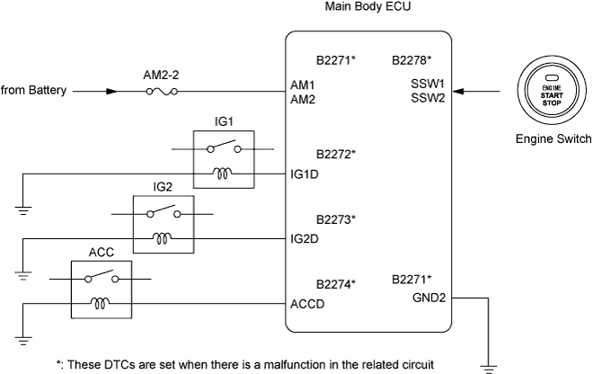

INSPECTION PROCEDURE
| 1. CHECK WHETHER DTC OUTPUT RECURS |

Clear the DTCs.
- HINT:
- After all DTCs are cleared, check if the trouble occurs again 5 seconds after the engine switch is turned on (IG).
Check for DTCs again.
- OK:
- No DTC is output.
|
|
||||

| OK | |
 |
| 2. CHECK BASIC FUNCTION |
Ensure the electrical key is inside the cabin.
Check that the engine switch indicator illuminates in green when the shift lever is in P or N and the brake pedal is depressed.
- OK:
- Engine switch indicator illuminates in green.
|
|
||||

| OK | |
|
| 3. INSPECT FUSE (AM2-2) |
Remove the AM2-2 fuse from the No. 1 relay block.
Check the fuse resistance.
- Standard resistance:
- Below 1 Ω
|
|
||||
| OK | |
|
| 4. READ VALUE USING INTELLIGENT TESTER (RELAY MONITOR) |
Connect the intelligent tester to the DLC3.
Turn the engine switch on (IG) and turn the tester ON.
Select the following menu items: Body / Main Body ECU / Data List / IG1 Relay Mon2, IG2 Relay Mon2 and ACC Relay Monitor.
Read the display on the tester.
Main body ECU Tester Display
Measurement Item/Range
Normal Condition
Diagnostic Note
IG1 Relay Mon2
IG1 inner relay monitor / ON or OFF
ON: Engine switch on (IG)
OFF: Engine switch off
-
IG2 Relay Mon2
IG2 inner relay monitor / ON or OFF
ON: Engine switch on (IG)
OFF: Engine switch off
-
ACC Relay Monitor
ACC relay monitor / ON or OFF
ON: Engine switch on (ACC)
OFF: Engine switch off
-
- OK:
- When the engine switch is turned on (IG), IG1 Relay Mon2 is ON and IG2 Relay Mon2 is ON.
When the engine switch is turned on (ACC), ACC Relay Monitor is ON.
|
|
||||
| NG | |
|
| 5. INSPECT IG1 RELAY |
Inspect the IG1 relay.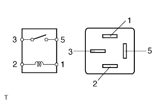
Remove the IG1 relay from the instrument panel junction block.
Measure the resistance according to the value(s) in the table below.
- Standard resistance:
Tester Connection
Specified Condition
3 - 5
10 kΩ or higher
3 - 5
Below 1 Ω
(when battery voltage is applied to terminals 1 and 2)
|
|
||||
| OK | |
|
| 6. INSPECT IG2 RELAY |
Inspect the IG2 relay.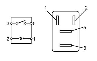
Remove the IG2 relay from the engine room No. 1 relay block.
Measure the resistance according to the value(s) in the table below.
- Standard resistance:
Tester Connection
Specified Condition
3 - 5
10 kΩ or higher
3 - 5
Below 1 Ω
(when battery voltage is applied to terminals 1 and 2)
|
|
||||
| OK | |
|
| 7. INSPECT ACC RELAY |
Inspect the ACC relay.
Remove the ACC relay from the engine room No. 5 relay block.
Measure the resistance according to the value(s) in the table below.
- Standard resistance:
Tester Connection
Specified Condition
3 - 5
10 kΩ or higher
3 - 5
Below 1 Ω
(when battery voltage is applied to terminals 1 and 2)
|
|
||||
| OK | |
|
| 8. CHECK WIRE HARNESS (IG2 RELAY - MAIN BODY ECU) |
Remove the IG2 relay from the engine room No. 1 relay block.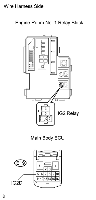
Disconnect the E19 main body ECU connector.
Measure the resistance according to the value(s) in the table below.
- Standard resistance:
Tester Connection
Specified Condition
Relay block IG2 relay terminal 1 - E19-5 (IG2D)
Below 1 Ω
Relay block IG2 relay terminal 2 - Body ground
Below 1 Ω
Relay block IG2 relay terminal 1 or E19-5 (IG2D) - Body ground
10 kΩ or higher
|
|
||||
| OK | |
|
| 9. CHECK WIRE HARNESS (ACC RELAY - MAIN BODY ECU) |
Remove the ACC relay from the No. 5 relay block.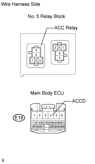
Disconnect the E18 main body ECU connector.
Measure the resistance according to the value(s) in the table below.
- Standard resistance:
Tester Connections
Specified Conditions
Relay block ACC relay terminal 1 - E18-4 (ACCD)
Below 1 Ω
Relay block ACC relay terminal 2 - Body ground
Below 1 Ω
Relay block ACC relay terminal 1 or E18-4 (ACCD) - Body ground
10 kΩ or higher
|
|
||||
| OK | |
|
| 10. INSPECT ENGINE SWITCH ASSEMBLY |
Remove the engine switch.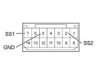
Measure the resistance of the switch.
- Standard resistance:
Tester Connection
Switch Condition
Specified Condition
7 (SS1) - 5 (GND)
Pushed
Below 1 Ω
2 (SS2) - 5 (GND)
Pushed
Below 1 Ω
7 (SS1) - 5 (GND)
Not pushed
10 kΩ or higher
2 (SS2) - 5 (GND)
Not pushed
10 kΩ or higher
|
|
||||
| OK | |
|
| 11. CHECK WIRE HARNESS (MAIN BODY ECU - BATTERY AND BODY GROUND) |
Disconnect the E18 and E19 main body ECU connectors.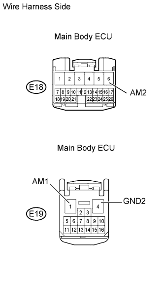
Measure the voltage and resistance according to the value(s) in the table below.
- Standard voltage:
Tester Connection
Specified Condition
E19-1 (AM1) - Body ground
10 to 14 V
E18-6 (AM2) - Body ground
10 to 14 V
- Standard resistance:
Tester Connection
Specified Condition
E19-4 (GND2) - Body ground
10 kΩ or higher
|
|
||||
| OK | ||
 |
||
| ||
| 12. CHECK WIRELESS DOOR LOCK AND UNLOCK OPERATION |
Check that the wireless door lock and unlock functions operate normally.
- OK:
- Wireless door lock and unlock functions operate normally.
|
|
||||
| OK | |
|
| 13. CHECK OPERATION OF ELECTRICAL KEY |
After replacing the electrical key with a normally functioning one, check that the wireless door lock and unlock functions operate normally.
- OK:
- Wireless door lock and unlock functions operate normally.
|
|
||||
| NG | |
|
| 14. PERFORM ACTIVE TEST USING INTELLIGENT TESTER (INDOOR ELECTRICAL KEY OSCILLATOR) |
Select the Active Test, use the intelligent tester to generate a control command, and then check that the oscillator operates.
Certification ECU Tester Display
Test Part
Control Range
Diagnostic Note
Fr Transmitter
Indoor electrical key oscillator (front)
ON / OFF
-
- OK:
- Indoor electrical key oscillator is ON.
|
|
||||
| NG | |
|
| 15. CHECK INDOOR ELECTRICAL KEY OSCILLATOR |
Ensure the electrical key is inside the cabin.
Replace the indoor electrical key oscillator with a new one.
Depress the brake pedal with the shift lever in P or N and check that the engine switch indicator illuminates in green.
- OK:
- Engine switch indicator illuminates in green.
|
|
||||
| OK | ||
|
||
| ||