C1243/43 Acceleration Sensor Stuck Malfunction
Diagnostic trouble codes · Vehicles built Jan 2007 – Jul 2007
Also covers:
- C1244/44 Open or Short in Deceleration Sensor Circuit
- C1245/45 Acceleration Sensor Output Malfunction
- C1279/79 Acceleration Sensor Output Voltage Malfunction (Test Mode DTC)
Versions by build date: Nov 2005 – Dec 2006 Jan 2007 – Jul 2007 from Aug 2007
DESCRIPTION
This sensor detects vehicle deceleration. The sensor signal is used in ABS control. If the sensor functions abnormally, the ABS warning light turns ON.DTC C1279/79 can be deleted when the deceleration sensor sends a deceleration sensor signal or the test mode ends. DTC C1279/79 is output only in the test mode.
| DTC No. |
DTC Detection Condition |
Trouble Area |
| C1243/43 |
While vehicle speed decreases from 30 km/h (18 mph) to 0 km/h (0 mph), condition that ECU terminal GL1 value does not change to 0.0294 G or more occurs 16 times consecutively. |
|
| C1244/44 |
When one of following conditions is met:
|
|
| C1245/45 |
At vehicle speed of 30 km/h (18 mph) or more, difference between back and forth G value calculated using G sensor signals and back and forth G value calculated using vehicle speed, exceeds 0.35 G for 60 seconds or more. |
|
| C1279/79 |
Detected only during test mode |
|
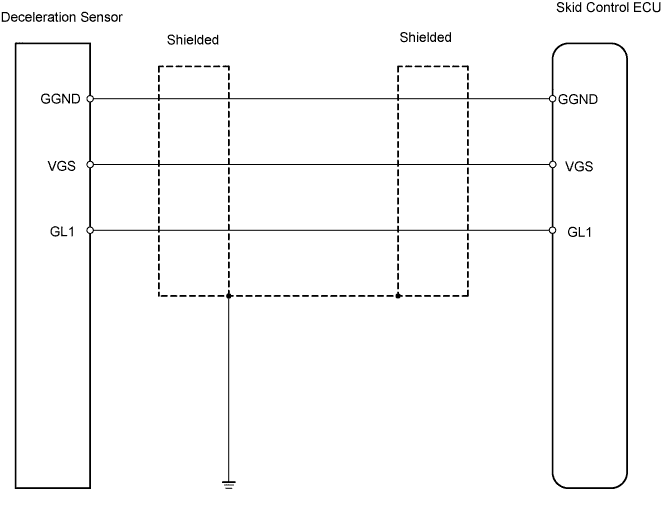
WIRING DIAGRAM

INSPECTION PROCEDURE
| 1. READ VALUE USING INTELLIGENT TESTER (DECELERATION SENSOR) |

Check the Data List for proper functioning of the deceleration sensor.
Skid control ECU Item
Measurement Item / Range (Display)
Normal Condition
Diagnostic Note
Deceleration Sensor
Deceleration sensor reading / Min.: -1.869 G, Max.: 1.869 G
Approx. 0 +-0.13 G when vehicle is not moving
Reading changes when vehicle is shaken
- OK:
- Deceleration value changes.
|
|
||||

| NG | |
 |
| 2. INSPECT DECELERATION SENSOR |
Remove the deceleration sensor.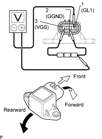
Connect 3 dry cell batteries of 1.5 V in series.
- HINT:
- Do not apply 6 V or more to terminals 3 (VGS) and 2 (GGND).
Check the output voltage of terminal 1 (GL1) when the sensor is tilted forward and rearward.
- Standard voltage:
Tester Connection
Sensor Position
Specified Condition
1 (GL1) - Battery's negative (-) lead
Horizontal
Approx. 2.3 V
1 (GL1) - Battery's negative (-) lead
Tilted forward
Approx. 0.4 to 2.3 V
1 (GL1) - Battery's negative (-) lead
Tilted rearward
Approx. 2.3 to 4 V
- HINT:
- If the sensor is tilted too much, it may output the wrong value.
- If the voltage drops, the sensor should be replaced with a new one.
- When replacing the sensor, it should not be placed upside down.
- If the sensor is tilted too much, it may output the wrong value.
|
|
||||
| OK | |
|
| 3. CHECK WIRE HARNESS (SKID CONTROL ECU - DECELERATION SENSOR) |
Disconnect the A27 ECU connector.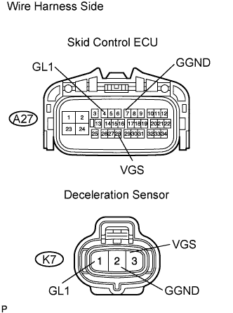
Disconnect the K7 sensor connector.
Measure the resistance of the wire harness side connectors.
- Standard resistance:
Tester Connection
Specified Condition
A27-4 (GL1) - K7-1 (GL1)
Below 1 Ω
A27-7 (GGND) - K7-2 (GGND)
Below 1 Ω
A27-28 (VGS) - K7-3 (VGS)
Below 1 Ω
K7-1 (GL1) - Body ground
10 kΩ or higher
K7-2 (GGND) - Body ground
10 kΩ or higher
K7-3 (VGS) - Body ground
10 kΩ or higher
|
|
||||
| OK | |
|
| 4. CHECK FOR DTC |
Install the deceleration sensor to the vehicle.
Clear the DTCs (Click here).
Drive the vehicle at 6 km/h (4 mph) or more.
Check for DTCs (Click here).
Result Result
Proceed to
DTC is output
A
DTC is not output
B
|
|
||||
| A | ||
 |
||
| ||