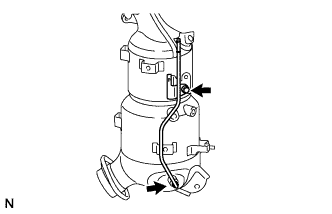
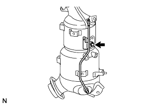
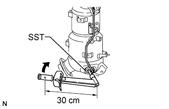
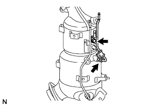
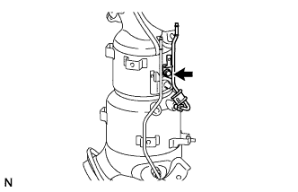
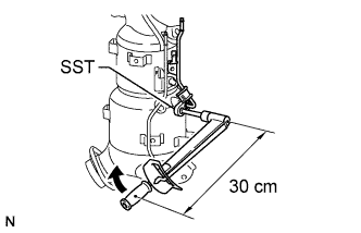
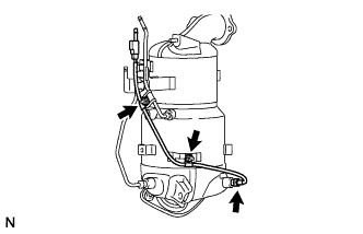
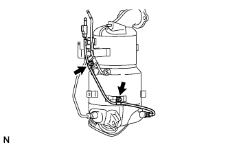
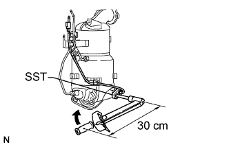
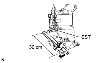
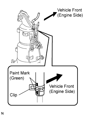
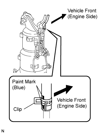
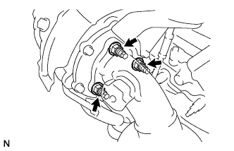
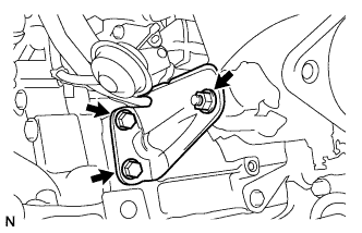
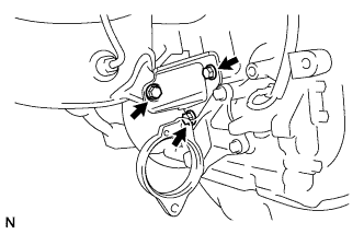
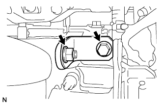
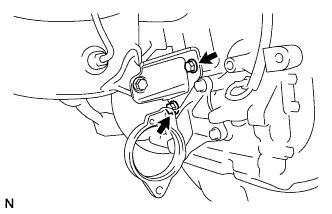
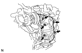
Temporarily install a new gasket and the exhaust manifold converter with the 3 nuts.
Temporarily install the No. 2 exhaust manifold stay LH with the 2 bolts and nut.
Temporarily install the No. 2 manifold stay RH with the 3 bolts.
Temporarily install the No. 1 manifold stay with the bolt and nut.
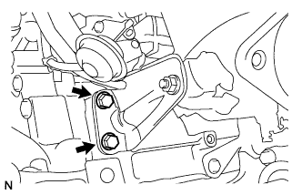
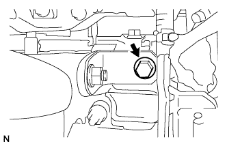
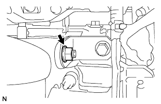
Tighten the 2 bolts holding the No. 2 exhaust manifold stay to the cylinder block (upper bolt → lower bolt).
Torque:
56 N*m{
571 kgf*cm
, 41 ft.*lbf
}
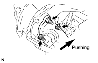
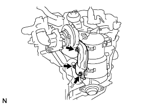
While pushing the manifold converter towards the cylinder block, tighten the 3 nuts holding the exhaust manifold converter to the turbocharger.
Torque:
25 N*m{
255 kgf*cm
, 18 ft.*lbf
}
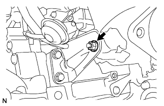
Tighten the nut holding the No. 2 exhaust manifold stay to the exhaust manifold converter.
Torque:
56 N*m{
571 kgf*cm
, 41 ft.*lbf
}
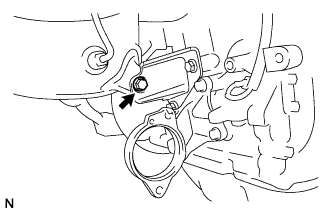
Tighten the bolt holding the No. 2 manifold stay to the exhaust manifold converter.
Torque:
56 N*m{
571 kgf*cm
, 41 ft.*lbf
}
HINT:
Ensure that the stay is pushed flush to the cylinder block and manifold converter while tightening.
Tighten the 2 bolts holding the No. 2 manifold stay to the cylinder block.
Torque:
56 N*m{
571 kgf*cm
, 41 ft.*lbf
}
Tighten the bolt holding the No. 1 manifold stay to the cylinder head.
Torque:
25 N*m{
255 kgf*cm
, 18 ft.*lbf
}
HINT:
Ensure that the stay is pushed flush to the cylinder head and manifold converter while tightening.
Tighten the nut holding the No. 1 manifold stay to the exhaust manifold converter.
Torque:
25 N*m{
255 kgf*cm
, 18 ft.*lbf
}
8.
INSTALL NO. 2 MANIFOLD CONVERTER INSULATOR
Install the manifold converter insulator with the 3 nuts.
Torque:
28.5 N*m{
291 kgf*cm
, 21 ft.*lbf
}
9.
INSTALL NO. 1 MANIFOLD CONVERTER INSULATOR
Install the manifold converter insulator with the 5 bolts.
Torque:
28.5 N*m{
291 kgf*cm
, 21 ft.*lbf
}
10.
INSTALL ENGINE ASSEMBLY
Install the engine assembly to the vehicle (Click here).
11.
CONNECT CABLE TO NEGATIVE BATTERY TERMINAL
12.
PERFORM CATALYST RECORD OF DPNR THERMAL DETERIORATION CLEAR FUNCTION
NOTICE:
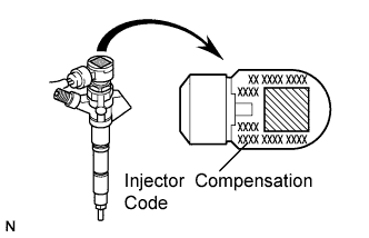
Injector compensation codes are unique, 30-digit, alphanumeric values printed on the head portion of each injector. If an incorrect injector compensation code is input into the ECM, the engine may rattle or engine idling may become rough. In addition, engine failure may occur and the life of the engine may be shortened.
HINT:
The following operation is available with ECMs that can transmit the registered injector compensation codes and catalyst record of DPNR thermal deterioration to the intelligent tester.
Read the catalyst record of DPNR thermal deterioration.
Connect the intelligent tester to the DLC3.
Turn the ignition switch on (IG) and turn the tester ON.
NOTICE:
Do not start the engine.
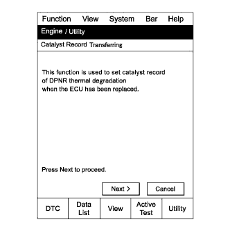
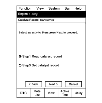
Enter the following menus: Powertrain / Engine and ECT / Utility / Catalyst Record Transferring.
Press "Next".
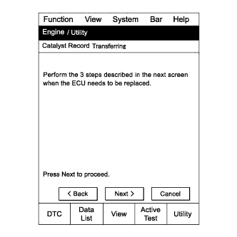
Press "Next" again to proceed.
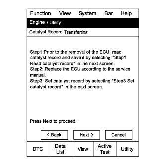
Press "Next" again to proceed.
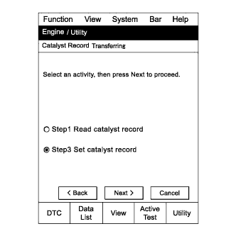
Select "Step 1 Read catalyst record".
Press "Next".
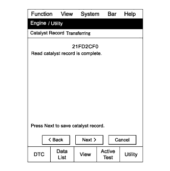
Confirm the catalyst record and press "Next".
NOTICE:
If a code cannot be read, replace the DPNR catalyst with a new one.
HINT:
When installing a new ECM that has a registered catalyst record such as "FFFFFFFF", perform the procedures below by following the prompts on the tester screen.
When replacing only the ECM, be sure to transfer the catalyst record from the removed ECM to the new ECM.
When replacing the DPNR catalyst, clear the catalyst record registered in the ECM (Click here).
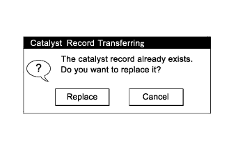
If the catalyst record has already been stored in the tester, the message in the illustration will appear. Press "Replace".
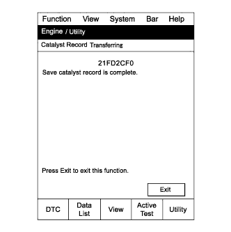
Press "Exit".
Read the injector compensation codes.
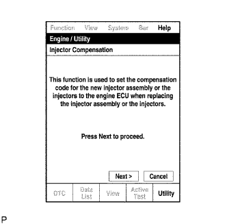
Enter the following menus: Powertrain / Engine and ECT / Utility / Injector Compensation.
Press "Next".
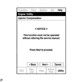
Press "Next" again to proceed.
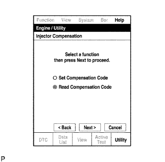
Select "Read Compensation Code".
Press "Next".
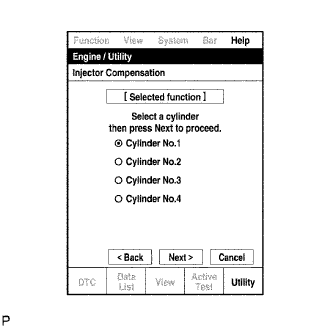
Select the number of the cylinder corresponding to the injector compensation code that you want to read.
Press "Next".
HINT:
The reading process may fail due to a problem with the wire harness or a bad connection with the DLC3. Check the wire harness and the DLC3 connection. If no problem is found, the ECM may be malfunctioning. Check the ECM and repeat this operation.
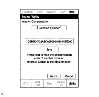
Check that the injector compensation code (30-digit alphanumeric value) is displayed on the tester screen.
Press "Save".
Check that the compensation code displayed on the tester screen is correct.
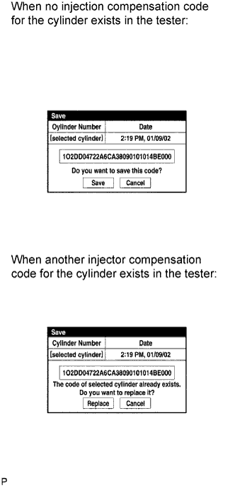
Press "Save" or "Replace" to save the injector compensation code.
HINT:
The existing compensation code is overwritten with the new compensation code and is deleted from the tester.
The saving process may fail due to a problem with the wire harness or a bad connection with the DLC3. Check the wire harness and the DLC3 connection. If no problem is found, the ECM may be malfunctioning. Check the ECM and repeat this operation.
To read and save injector compensation codes for other cylinders, press "Next" to continue. To finish this operation, press "Cancel".
Turn the ignition switch off and turn the tester OFF.
Set the catalyst record of DPNR thermal deterioration.
Connect the intelligent tester to the DLC3.
Turn the ignition switch on (IG) and turn the tester ON.
Enter the following menus: Powertrain / Engine and ECT / Utility / Catalyst Record Transferring
Press "Next".
Press "Next" again to proceed.
Press "Next" again to proceed.
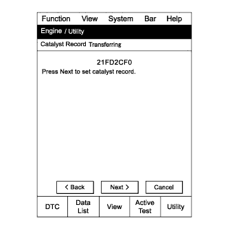
Select "Step 3 Set catalyst record".
Confirm the catalyst record and press "Next".
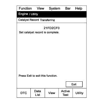
Press "Exit".
Set the injector compensation code.
NOTICE:
Do not start the engine.
HINT:
The injector compensation code is imprinted on the head portion of each injector.
Enter the following menus: Powertrain / Engine and ECT / Utility / Injector Compensation.
Press "Next".
Press "Next" again to proceed.
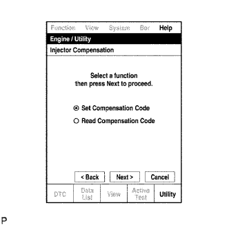
Select "Set Compensation Code".
Press "Next".
Select the number of the cylinder corresponding to the injector compensation code that you want to read.
Press "Next".
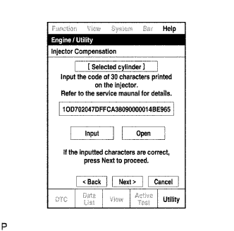
Check that the compensation code displayed on the screen is correct, by comparing it with the 30-digit alphanumeric value on the head portion of the injector.
NOTICE:
If an incorrect injector compensation code was input into the ECM, the engine may rattle or engine idling may become rough. In addition, engine failure may occur and the life of the engine may be shortened.
HINT:
If a wrong compensation code was input or read, return to the "Input Value" screen by pressing "Input". The saving process may fail due to a problem with the wire harness or a bad connection with the DLC3. Check the wire harness and the DLC3 connection. If no problem is found, the ECM may be malfunctioning. Check the ECM and repeat this operation.
Press "Next" to set the compensation code to the ECM.
HINT:
If the setting fails, the compensation code may be incorrect. Check the compensation code again.
If the attempted compensation code is correct, a problem with the wire harness or a bad connection with the DLC3 may cause the failure. Check the wire harness and the DLC3 connection. If no problem is found, the ECM may be malfunctioning. Check the ECM and repeat this operation.
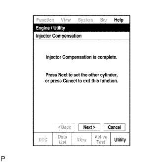
To continue with compensation code registrations for other cylinders, press "Next". To finish the registration, press "Cancel".
Clear DTC P1601 stored in the ECM using the tester.
Turn the ignition switch off and turn the tester OFF.
Wait for at least 30 seconds.
Turn the ignition switch on (IG) and turn the tester ON.