C2195/95 Multi-receiver Antenna Circuit (Test Mode DTC)
Diagnostic trouble codes · Vehicles built from Nov 2005
DESCRIPTION
| DTC No. |
DTC Detection Condition |
Trouble Area |
| C2195/95 |
In test mode, tire pressure antenna circuit malfunction occurs |
|
WIRING DIAGRAM
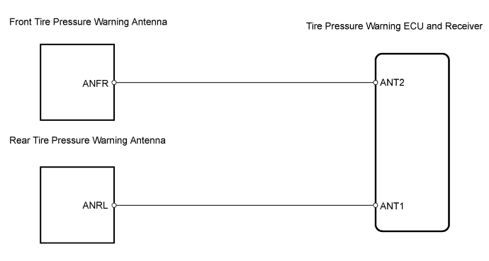

INSPECTION PROCEDURE
| 1. PERFORM FORCED TRANSMISSION OF TRANSMITTER ID OF ALL WHEELS |

Set the pressure of each tire to the specified value.
- Standard pressure: :
- 220 kPa (2.2 kgf /cm2, 32 psi)
Connect the intelligent tester to the DLC3.
Select tirepress by following the prompts displayed on the intelligent tester.
- Tire pressure warning ECU and receiver:
Item
Measurement Item / Range (Display)
Normal Condition
Diagnostic Note
Tirepress1
ID1 tire pressure/ minimum: 0 kPa (0 kgf/cm2, 0 psi) maximum: 637.5 kPa (6.5 kgf/cm2, 92.5 psi)
Actual tire pressure
-
Tirepress2
ID2 tire pressure/ minimum: 0 kPa (0 kgf/cm2, 0 psi) maximum: 637.5 kPa (6.5 kgf/cm2, 92.5 psi)
Actual tire pressure
-
Tirepress3
ID3 tire pressure/ minimum: 0 kPa (0 kgf/cm2, 0 psi) maximum: 637.5 kPa (6.5 kgf/cm2, 92.5 psi)
Actual tire pressure
-
Tirepress4
ID4 tire pressure/ minimum: 0 kPa (0 kgf/cm2, 0 psi) maximum: 637.5 kPa (6.5 kgf/cm2, 92.5 psi)
Actual tire pressure
-
- NOTICE:
- It may take up to 1 minute to display the updated data.
Rapidly release the tire pressure from any tire to 40 kPa (0.4 kgf/cm2, 5.8 psi) / 30seconds or more.
- HINT:
- Identify the malfunctioning tire pressure warning valve and transmitter by rapidly releasing the tire pressures from each tire.
- Record which tirepress data (ID1 to ID4) corresponds to each tire.
- Identify the malfunctioning tire pressure warning valve and transmitter by rapidly releasing the tire pressures from each tire.
Check the Data List.
- Result:
Result
Proceed to
All tirepress data does not change (front side)
A
All tirepress data does not change (rear side)
B
All tirepress data (ID1 to ID4) changes
C
|
|
||||
|
|
||||


| A | |
 |
| 2. CHECK WIRE HARNESS (ECU - FRONT TIRE PRESSURE WARNING ANTENNA) |
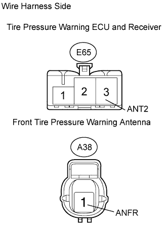 |
Disconnect the E65 ECU connector.
Disconnect the A38 antenna connector.
Measure the resistance of the wire harness side connectors.
- Standard resistance:
Tester Connection
Specified Condition
E65-3 (ANT2) - A38-1 (ANFR)
Below 1 Ω
|
|
||||
| OK | |
|
| 3. REPLACE FRONT TIRE PRESSURE WARNING ANTENNA |
| NEXT | |
|
| 4. CHECK TEST MODE DTC |
Check test mode DTC (Click here).
- OK:
- DTC is not output
|
|
||||
| OK | ||
 |
||
| ||
| 5. CHECK WIRE HARNESS (ECU - REAR TIRE PRESSURE ANTENNA) |
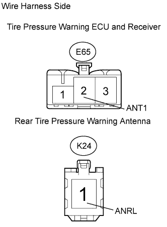 |
Disconnect the E65 ECU connector.
Disconnect the K24 antenna connector.
Measure the resistance of the wire harness side connectors.
- Standard resistance:
Tester Connection
Specified Condition
E65-2 (ANT1) - K24-1 (ANRL)
Below 1 Ω
|
|
||||
| OK | |
|
| 6. REPLACE REAR TIRE PRESSURE WARNING ANTENNA |
| NEXT | |
|
| 7. CHECK TEST MODE DTC |
Check test mode DTC (Click here).
- OK:
- DTC is not output
|
|
||||
| OK | ||
|
||
| ||