REASSEMBLY
Removal / installation · Vehicles built Nov 2005 – Dec 2006
Versions by build date: Nov 2005 – Dec 2006 Jan 2007 – Jul 2007 from Aug 2007
- HINT:
- Use the same procedures for the LH side and RH side.
- The procedures listed below are for the LH side.
| 1.
APPLY HIGH TEMPERATURE GREASE |
 |
Apply high temperature grease to the contact surface of the shoe and backing plate.
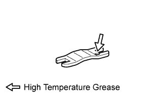
| 2.
INSTALL PARKING BRAKE SHOE LEVER LH |
|
| 3.
INSTALL NO. 2 PARKING BRAKE SHOE ASSEMBLY LH |
|
Connect the parking brake cable to the parking brake shoe lever.
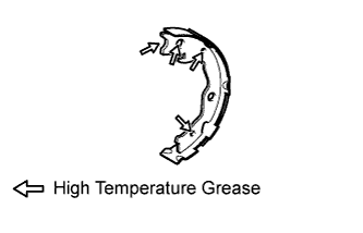
- Apply high temperature grease to the following contact surfaces of the shoe.
- Shoe to anchor pin
- Shoe to parking brake lever pin
- Shoe to spring
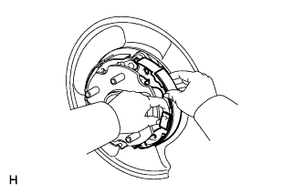
- Install the shoe with the shoe hold-down spring and pin.
| 4.
INSTALL NO. 1 PARKING BRAKE SHOE ASSEMBLY LH |
|
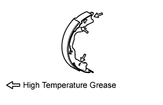
- Apply high temperature grease to the following contact surfaces of the shoe.
- Shoe to anchor pin
- Shoe to spring
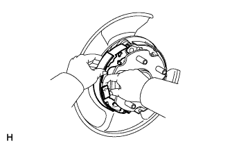
- Install the shoe with the shoe hold-down spring and pin.
| 5.
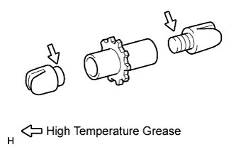
INSTALL PARKING BRAKE SHOE ADJUSTING SCREW SET |
|
- Apply high temperature grease to the adjusting bolt.
Install the screw set.
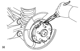
| 6.
INSTALL PARKING BRAKE SHOE RETURN TENSION SPRING (for Lower Side) |
|
Using needle-nose pliers, install the tension spring.
| 7.
INSTALL PARKING BRAKE SHOE STRUT LH |
|
- Apply high temperature grease to the contact surface of the strut and shoe return tension spring.
Install the strut.
| 8.
INSTALL PARKING BRAKE SHOE RETURN TENSION SPRING (for Upper Side) |
|
- Using needle-nose pliers, install the 2 shoe return tension springs.
| 9.
CHECK PARKING BRAKE INSTALLATION |
|
Check that each part is installed properly.
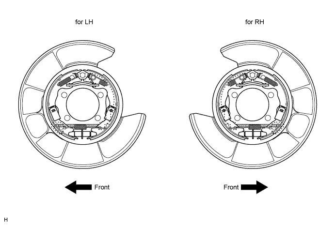

- NOTICE:
- There should be no oil or grease adhering to the friction surface of the shoe lining and disc.
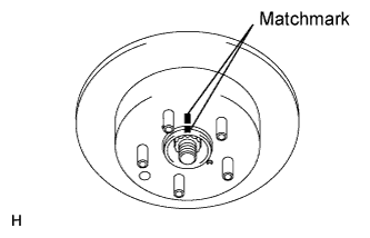
| 10.
INSTALL REAR DISC |
|
- Align the matchmarks and install the disc.
- HINT:
- When replacing the disc with new one, select the installation position where the disc has the minimum runout.
| 11.
ADJUST PARKING BRAKE SHOE CLEARANCE |
|
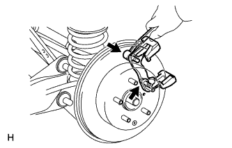
Temporarily install the hub nuts.
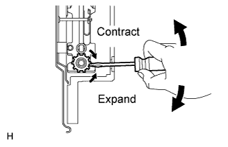
- Remove the shoe adjusting hole plug, and then turn the adjuster to expand the shoe adjuster until the disc locks.
Turn and contact the shoe adjuster until the disc can rotate smoothly.
- Standard return notch:
- 8 notches
Check that the shoe has no brake drag.
| 12.
INSTALL PARKING BRAKE SHOE ADJUSTING HOLE PLUG |
|
Install the shoe adjusting hole plug to the rear disc.
| 13.
CONNECT REAR DISC BRAKE CYLINDER MOUNTING LH
|
|
- Install the cylinder mounting with the 2 bolts.
-
Torque:
- 88 N*m{
897 kgf*cm
, 65 ft.*lbf
}
| 14.
INSTALL REAR WHEEL |
|
-
Torque:
- 103 N*m{
1,050 kgf*cm
, 76 ft.*lbf
}
| 15.
DRIVE VEHICLE |
|
Pull the parking brake lever with a force of 147 N (15 kgf, 33 lbf).
Drive the vehicle at approximately 50 km/h (31 mph) for approximately 400 m (0.25 miles).
- NOTICE:
- Drive the vehicle on a safe, level and dry road.
Repeat the above steps 2 or 3 times.
| 16.
CHECK PARKING BRAKE LEVER TRAVEL
|
|
Pull the lever upward with a force of approximately 200 N (20 kgf, 44 lbf) and count the number of clicks.
- OK:
- 7 to 9 clicks (without rear brake dragging)
| 17.
ADJUST PARKING BRAKE LEVER TRAVEL
|
|
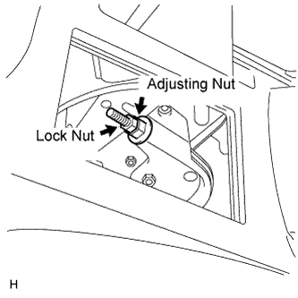
- Turn the No. 1 wire adjusting nut until the lever travel is correct.
- OK:
- 7 to 9 clicks (without rear brake dragging)
<Lever pulling force: approximately 200 N (20 kgf, 44 lbf)>
Tighten the lock nut.
-
Torque:
- 6.0 N*m{
61 kgf*cm
, 53 in.*lbf
}
Operate the parking brake lever 3 to 4 times, and check the parking brake lever travel.
- OK:
- 7 to 9 clicks (without rear brake dragging)
<Lever pulling force: approximately 200 N (20 kgf, 44 lbf)>
When operating the parking brake lever, check that the brake warning light illuminates at the first click.
- Standard condition:
- Brake warning light always illuminates at the first click.