REPLACEMENT
Removal / installation · Vehicles built from Aug 2007
| 1. DISCONNECT CABLE FROM NEGATIVE BATTERY TERMINAL |

- CAUTION:
- Wait at least 90 seconds after disconnecting the cable from the negative (-) battery terminal to prevent airbag and seat belt pretensioner activation.
| 2. REMOVE REAR CONSOLE BOX SUB-ASSEMBLY |
Remove the rear console box sub-assembly (Click here).
| 3. REMOVE BATTERY CLAMP SUB-ASSEMBLY |
Remove the bolt and loosen the nut.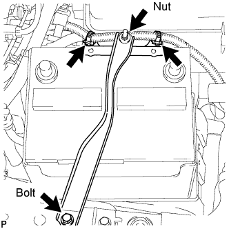

Detach the 2 wire harness clamps.
Detach the hook of the battery clamp from the front battery bracket, and then remove the battery clamp.
| 4. REMOVE BATTERY |
| 5. REMOVE FRONT BATTERY BRACKET |
Detach the 2 wire harness clamps.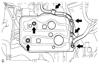
Remove the 4 bolts and front bracket.
| 6. REMOVE BATTERY BRACKET REINFORCEMENT |
Remove the 2 bolts and bracket reinforcement.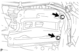
| 7. REMOVE AIR CLEANER CAP SUB-ASSEMBLY |
Disconnect the mass air flow meter connector.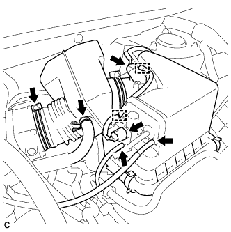
Disconnect the VSV (air intake control) connector.
Disconnect the 2 wire harness clamps and 2 vacuum hoses.
Disconnect the No. 2 ventilation hose from the air cleaner hose.
Loosen the No. 1 air cleaner hose clamp.
Unfasten the 2 hook clamps, and then remove the air cleaner cap.
Remove the air cleaner filter element from the air cleaner case.
| 8. REMOVE AIR CLEANER CASE |
Disconnect the harness clamp.
Remove the 3 bolts and air cleaner case.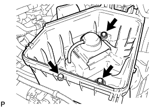
| 9. REMOVE TRANSMISSION CONTROL CABLE ASSEMBLY |
Remove the nut and disconnect the transmission control cable assembly from the control shaft lever.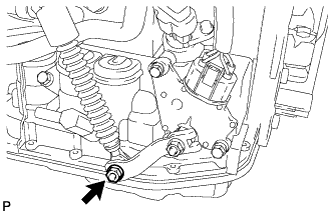
Remove the clip and disconnect the transmission control cable assembly from the control cable bracket.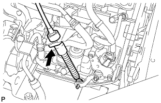
Disconnect the transmission control cable assembly from the control cable support.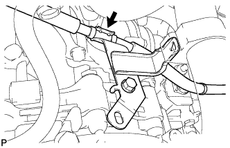
Remove the bolt and disconnect the clamp of the transmission control cable assembly.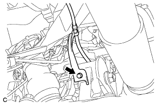
Disconnect the transmission control cable assembly from the shift lever.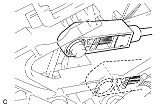
Turn the nut and disconnect the transmission control cable assembly from the shift lever retainer.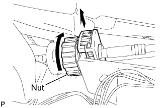
Remove the 2 bolts and transmission control cable assembly.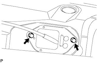
| 10. INSTALL TRANSMISSION CONTROL CABLE ASSEMBLY |
Install the transmission control cable assembly with the 2 bolts.
- Torque:
- 5.0 N*m{ 51 kgf*cm , 44 in.*lbf }
Turn the nut of the transmission control cable assembly and push in the lock.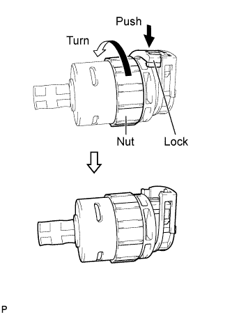
Install the transmission control cable assembly onto the shift lever retainer.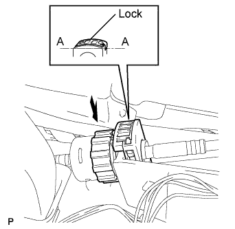
- HINT:
- Install the cable with the protrusion on the outer part of the cable facing upward.
- After installing, check that the lock of the outer part of the cable protrusion above the A-A line, as shown in the illustration.
- Install the cable with the protrusion on the outer part of the cable facing upward.
Connect the transmission control cable assembly to the shift lever.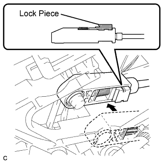
- HINT:
- Check that the lock piece is pulled outward.
- Install the cable end all the way to the base of the pin.
- Check that the lock piece is pulled outward.
Push the lock piece into the adjuster case.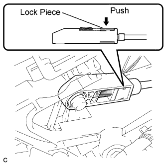
- HINT:
- Securely push in the lock piece until the slider lock is engaged.
Install the transmission control cable assembly onto the control cable bracket with a new clip.
Connect the transmission control cable assembly onto the control shaft lever with the nut.
- Torque:
- 12 N*m{ 122 kgf*cm , 9 ft.*lbf }
Connect the clamp of the transmission control cable assembly with the bolt.
- Torque:
- 5.0 N*m{ 51 kgf*cm , 44 in.*lbf }
Connect the transmission control cable assembly to the cable support.
| 11. INSTALL AIR CLEANER CASE |
Install the air cleaner case with the 3 bolts.
- Torque:
- 5.0 N*m{ 51 kgf*cm , 44 in.*lbf }
Connect the harness clamp.
| 12. INSTALL AIR CLEANER CAP SUB-ASSEMBLY |
Install the air cleaner filter element onto the air cleaner case.
Insert the hinge part of the air cleaner cap into the air cleaner case, then hang the 2 hook clamps.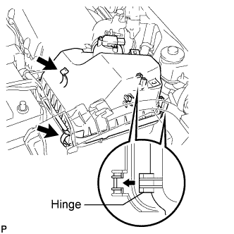
Tighten the No. 1 air cleaner hose clamp.
Connect the No. 2 ventilation hose to the air cleaner hose.
Connect the 2 wire harness clamps and 2 vacuum hoses.
Connect the VSV (intake air control) connector.
Connect the mass air flow meter connector.
| 13. INSTALL BATTERY BRACKET REINFORCEMENT |
Install the bracket reinforcement with the 2 bolts.
- Torque:
- 19 N*m{ 194 kgf*cm , 14 ft.*lbf }
| 14. INSTALL FRONT BATTERY BRACKET |
Install the front battery bracket with the 4 bolts.
- Torque:
- 19 N*m{ 194 kgf*cm , 14 ft.*lbf }
Attach the 2 wire harness clamps.
| 15. INSTALL BATTERY |
| 16. INSTALL BATTERY CLAMP SUB-ASSEMBLY |
Attach the hook of the battery clamp to the front battery bracket.
Temporarily tighten the nut and install the bolt.
Adjust the battery clamp position.
Fully tighten the nut and bolt.
- Torque:
- Bolt:
- 17 N*m{ 170 kgf*cm , 12 ft.*lbf }
- Nut:
- 4.9 N*m{ 50 kgf*cm , 43 in.*lbf }
Attach the 2 wire harness clamps.
| 17. CONNECT CABLE TO NEGATIVE BATTERY TERMINAL |
| 18. INSPECT SHIFT LEVER POSITION |
When shifting the lever from the P position to the R position with the ignition switch in the ON position and the brake pedal depressed, make sure that the shift lever moves smoothly and correctly into position.
Start the engine and make sure that the vehicle moves forward after shifting the lever from the N position to the D position and moves rearward after shifting the lever to the R position.
If the operation cannot be performed as specified, inspect the park/neutral position switch and check the shift lever installation condition.
| 19. ADJUST SHIFT LEVER POSITION |
Apply the parking brake and move the shift lever to the N position.
Remove the rear console box sub-assembly (Click here).
Disconnect the end of the transmission control cable assembly from the shift lever assembly.
Turn the lock nut counterclockwise. While holding the lock nut, disconnect the transmission control cable from the shift lever retainer.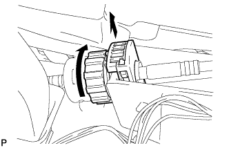
Slide the slider of the transmission control cable in the direction indicated by the arrow and pull the lock piece outward.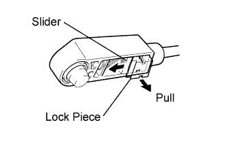
Turn the lock nut of the transmission control cable counterclockwise. While holding the lock nut, push in the lock.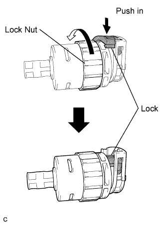
Connect the outer part of the transmission control cable to the shift lever retainer.
- HINT:
- Install the cable with the protrusion on the outer parts of the cable facing upward.
- After installation, check that the outer part of the cable protrudes above the A-A line as shown in the illustration.
- Install the cable with the protrusion on the outer parts of the cable facing upward.
Install the transmission control cable end to the shift lever assembly.
- HINT:
- Check that the lock piece is pulled outward.
- Install the cable end all the way to the base of the pin.
- Check that the lock piece is pulled outward.
Push the lock piece into the adjuster case.
- HINT:
- Securely push in the lock piece until the slider lock is engaged.
Install the rear console box sub-assembly (Click here).
| 20. INSTALL REAR CONSOLE BOX SUB-ASSEMBLY |
Install the rear console box sub-assembly (Click here).