Speedometer Malfunction
Circuit diagnosis · Vehicles built from Nov 2005
DESCRIPTION
The combination meter assembly controls the speedometer in accordance with vehicle speed signals from the ABS and traction actuator*1 (skid control ECU) or the brake actuator*2 (skid control ECU) through the CAN communication system.- HINT:
- *1: w/ VSC
- *2: w/o VSC
WIRING DIAGRAM
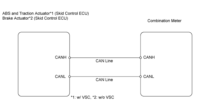

INSPECTION PROCEDURE
- HINT:
- If DTC U0129 has been stored, troubleshoot the CAN communication system first.
| 1. PERFORM ACTIVE TEST USING INTELLIGENT TESTER (Speed Meter Operation) |

Connect the intelligent tester to the DLC3.
Turn the ignition switch on (IG) and turn the tester ON.
Perform the ACTIVE TEST according to the prompts displayed on the tester.
Combination meter Item
Measurement Item / Range (Display)
Diagnostic Note
Speed Meter Operation
0 / 40 / 80 / 120 / 160 / 200 / 240 km
Value selected during Active Test is displayed
- OK:
- Vehicle speed displayed on the tester is almost the same as that of the speedometer reading.
|
|
||||

| OK | |
 |
| 2. READ VALUE USING DATA LIST (Vehicle Speed Meter) |
Connect the intelligent tester to the DLC3.
Turn the ignition switch on (IG) and the tester ON.
Read the Data List according to the prompts displayed on the tester.
Combination meter Item
Tester Details
Normal Condition
Diagnostic Note
Vehicle Speed Meter
Vehicle speed / Min.: 0 km/h (0 mph), Max.: 255 km/h (158 mph)
Almost same as actual vehicle speed (When driving)
-
|
|
||||
| OK | ||
 |
||
| ||