Back Door Courtesy Switch Circuit
Circuit diagnosis · Vehicles built from Nov 2005
DESCRIPTION
The radio and navigation assembly receives a back door condition signal from the back door courtesy light switch.WIRING DIAGRAM
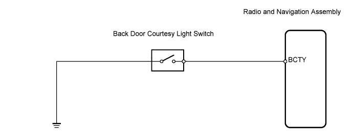

INSPECTION PROCEDURE
| 1. INSPECT BACK DOOR COURTESY LIGHT SWITCH ASSEMBLY |

Measure the resistance of the switch.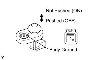
- Standard resistance:
Tester Connection
Condition
Specified Condition
K18-1 - Body ground
Not pushed (ON)
Below 1 Ω
K18-1 - Body ground
Pushed (OFF)
10 kΩ or higher
|
|
||||

| OK | |
 |
| 2. CHECK WIRE HARNESS (RADIO AND NAVIGATION ASSEMBLY - BACK DOOR COURTESY LIGHT SWITCH) |
Disconnect the E54 radio connector.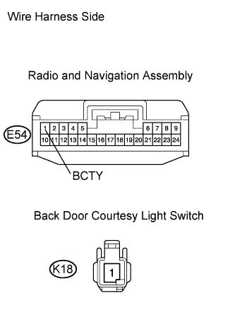
Disconnect the K18 switch connector.
Measure the resistance of the wire harness side connectors.
- Standard resistance:
Tester Connection
Specified Condition
E54-1 (BCTY) - K18-1
Below 1 Ω
E54-1 (BCTY) - Body ground
10 kΩ or higher
|
|
||||
| OK | |
|
| 3. CHECK RADIO AND NAVIGATION ASSEMBLY (BCTY VOLTAGE) |
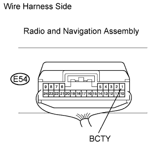 |
Reconnect the E54 radio connector.
Reconnect the K18 switch connector.
Check the voltage of the radio.
- Standard voltage:
Tester Connection
Condition
Specified Condition
E54-1 (BCTY) - Body ground
Ignition switch on (ACC)
10 to 14 V
|
|
||||
| OK | ||
 |
||
| ||