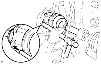
Coat the spline of the inboard joint shaft with gear oil.
Using a brass bar and hammer, align the shaft splines in the drive shaft.
NOTICE:
Set the snap ring with the opening side facing downwards.
Be careful not to damage the oil seal, boot and dust cover.
2.
INSTALL FRONT DRIVE SHAFT ASSEMBLY RH
Coat the spline of the inboard joint shaft with gear oil.
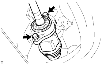
Align the shaft spline and install the drive shaft with 2 bolts.
Torque:
63.7 N*m{
650 kgf*cm
, 47 ft.*lbf
}
NOTICE:
Do not damage the oil seal, boot and dust cover.
3.
CONNECT STEERING KNUCKLE WITH AXLE HUB LH
Align the shaft splines in the drive shaft to the steering knuckle with axle hub.
4.
CONNECT STEERING KNUCKLE WITH AXLE HUB RH
HINT:
Use the same procedures described for the LH side.
5.
CONNECT FRONT SUSPENSION NO. 1 LOWER ARM SUB-ASSEMBLY LH
Connect the lower arm to the ball joint with the 2 bolts and nut.
Torque:
92 N*m{
938 kgf*cm
, 68 ft.*lbf
}
6.
CONNECT FRONT SUSPENSION NO. 1 LOWER ARM SUB-ASSEMBLY RH
HINT:
Use the same procedures described for the LH side.
7.
INSTALL FRONT STABILIZER LINK ASSEMBLY LH
Install the link with the 2 nuts.
Torque:
74 N*m{
755 kgf*cm
, 55 ft.*lbf
}
8.
INSTALL FRONT STABILIZER LINK ASSEMBLY RH
HINT:
Use the same procedures described for the LH side.
9.
CONNECT TIE ROD END SUB-ASSEMBLY LH
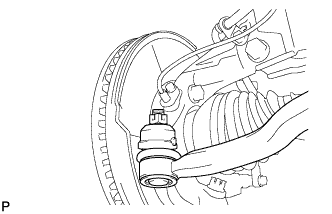
Connect the tie rod end onto the steering knuckle with the castle nut.
Torque:
49 N*m{
500 kgf*cm
, 36 ft.*lbf
}
NOTICE:
If the holes for the clip are not aligned, tighten the nut up to 60° further.
Install a new cotter pin.
10.
CONNECT TIE ROD END SUB-ASSEMBLY RH
HINT:
Use the same procedures described for the LH side.
11.
INSTALL FRONT SPEED SENSOR LH
NOTICE:
To prevent interference with other parts, do not twist the sensor wire's painted line areas when installing it.
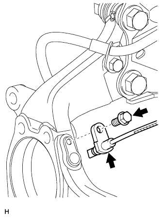
Set the sensor body to the knuckle, and then install the sensor with the bolt.
Torque:
8.5 N*m{
87 kgf*cm
, 75 in.*lbf
}
NOTICE:
Keep the sensor tip and sensor installation hole free from foreign matter.
Firmly insert the sensor body into the knuckle before tightening the bolt.
After installing the sensor to the knuckle, make sure that there is no clearance between the sensor stay and knuckle. Also make sure that no foreign matter is stuck between the parts.
To prevent interference between the sensor and magnetic rotor, do not rotate the sensor body during or after the insertion of the sensor body to the knuckle.
Install the sensor clamp and sensor clip as follows.
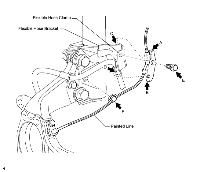
Set the flexible hose clamp on the flexible hose bracket.
Simultaneously perform the following: 1) hang the hook part of the sensor clamp (labeled A) on the part of the flexible hose bracket (labeled C); and 2) insert the hook part of the sensor clamp (labeled B) to the part of the flexible hose bracket (labeled D).
NOTICE:
Do not twist the sensor wire when installing the clamp.
Tighten together the sensor clamp and the flexible hose clamp to the flexible hose bracket with the bolt (labeled E).
Torque:
18.5 N*m{
189 kgf*cm
, 14 ft.*lbf
}
Insert the sensor clip (labeled F) into the hole on the absorber lower bracket.
Install the sensor clamp, and sensor clip as follows.
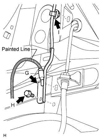
Set the sensor clamp (labeled G) on the side member, and then tighten it with the bolt (labeled H).
Torque:
8.5 N*m{
87 kgf*cm
, 75 in.*lbf
}
NOTICE:
Do not twist the sensor wire when installing the clamp.
Insert the sensor clip (labeled I) into the hole on the apron.
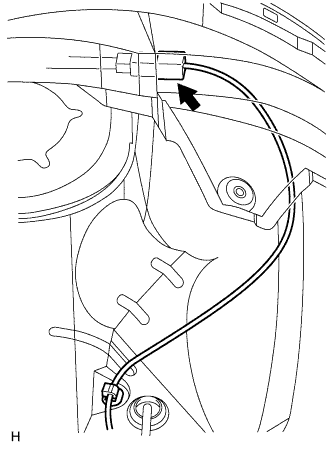
Connect the sensor connector.
12.
INSTALL FRONT SPEED SENSOR RH
HINT:
Use the same procedures described for the LH side.
13.
INSTALL FRONT AXLE HUB NUT
Install a new hub nut.
Torque:
216 N*m{
2,203 kgf*cm
, 159 ft.*lbf
}
for φ 26
292 N*m{
2,978 kgf*cm
, 215 ft.*lbf
}
for φ 30
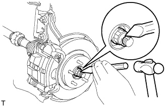
Using a chisel and hammer, stake the hub nut.
14.
INSTALL FRONT WHEEL
Torque:
103 N*m{
1,050 kgf*cm
, 76 ft.*lbf
}
15.
ADD AUTOMATIC TRANSAXLE FLUID
Fluid type:
Toyota Genuine ATF WS
16.
ADD TRANSAXLE OIL
Stop the vehicle in a level place.
Remove the transaxle filler plug and gasket.
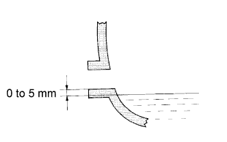
Check that the oil level is between 0 to 5 mm (0 to 0.20 in.) from the bottom lip of the filler plug opening. If the result is not as specified, add transaxle oil.
Oil grade:
GL-4
Viscosity:
SAE 75W
Standard capacity:
2.5 liters (2.6 US qts, 2.2 Imp. qts)
NOTICE:
Too much or too little oil will lead to transaxle problems.
After adjusting the oil level, drive the vehicle and check the oil level again.
Check for oil leakage if the oil level is low.
Install the transaxle filler plug and a new gasket.
Torque:
49 N*m{
500 kgf*cm
, 36 ft.*lbf
}
17.
CHECK FOR AUTOMATIC TRANSAXLE OIL LEAKAGE
18.
CHECK FOR TRANSAXLE OIL LEAKAGE
19.
INSPECT AND ADJUST FRONT WHEEL ALIGNMENT
Inspect and adjust the front wheel alignment (Click here).