7.
REMOVE PROPELLER WITH CENTER BEARING SHAFT ASSEMBLY
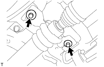
Remove the 2 bolts and 2 adjusting washers, and disconnect the propeller with center bearing shaft.
NOTICE:
During the removal, do not exert excessive force on the universal joint.
When removing, transporting or storing the propeller with center bearing shaft assembly, do not allow the No. 2 joint angle to exceed 20°.
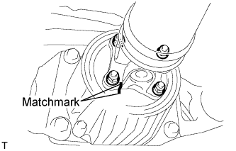
Place matchmarks on the differential carrier and propeller shaft.
Remove the 4 nuts and 4 washers, and disconnect the propeller shaft and differential carrier.
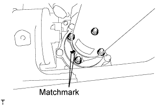
Place matchmarks on the transfer and propeller shaft.
Remove the 4 nuts and 4 washers, and disconnect the propeller shaft from the transfer.
8.
REMOVE REAR SUSPENSION MEMBER BRACE LH
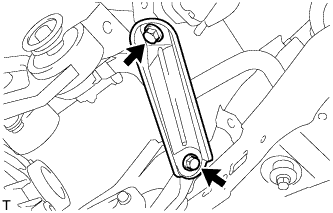
Remove the 2 bolts and brace from the suspension member.
9.
REMOVE REAR SUSPENSION MEMBER BRACE RH
HINT:
Use the same procedures described for the LH side.
10.
REMOVE DIFFERENTIAL CARRIER SUB-ASSEMBLY
Disconnect the harness clamp.
Remove the breather tube.
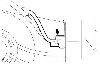
Disconnect the connector.
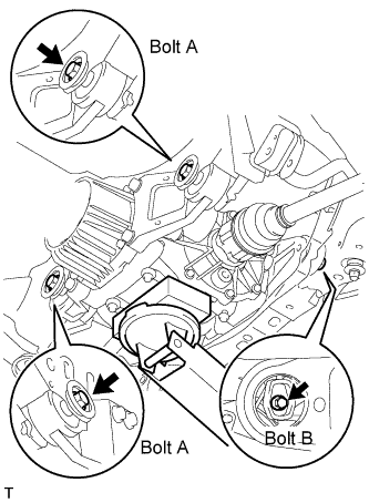
Support the rear differential carrier with a transmission jack or equivalent.
Remove the bolt labeled A and bolt labeled B.
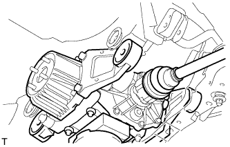
Slowly lower the jack and then tilt the rear differential carrier.
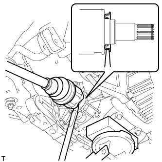
Set the tip of the tire lever to the position on the rear drive shaft inboard joint shown in the illustration. Then, using the ribbed part of the rear differential carrier as a fulcrum, disconnect the left and right rear drive shafts.
NOTICE:
Do not scratch the rear drive shaft dust cover.
11.
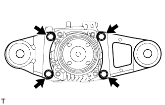
REMOVE REAR DIFFERENTIAL NO. 1 AND NO. 2 SUPPORT
Remove the 4 bolts and differential No. 1 and No. 2 supports from the differential carrier.
12.
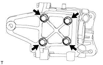
REMOVE REAR DIFFERENTIAL SUPPORT
Remove the 4 bolts and differential support from the differential carrier.
13.
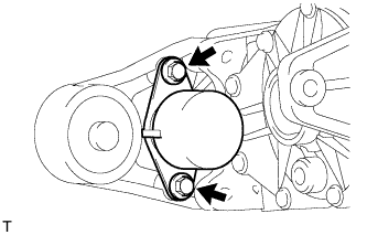
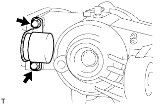
REMOVE REAR DIFFERENTIAL DYNAMIC DAMPER
Remove the 2 bolts and damper (front side) from the No. 1 support.
Remove the 2 bolts and damper (rear side) from the differential support.