| A |  |
| GO TO DTC CHART (Click here) |
DTC P0101 Mass or Volume Air Flow Circuit Range / Performance Problem |
| DTC Detection Drive Pattern | DTC Detection Condition | Trouble Area |
| After the engine is completely warmed up, perform the following procedure 3 times: from a vehicle speed of 60 km/h (37 mph), accelerate the vehicle to 80 km/h (50 mph), quickly release the accelerator pedal and do not depress it for 7 seconds or more. After performing the above procedure, immediately stop the vehicle and confirm that "Exhaust Temperature B1S1" displays 300°C (572°F) or higher using the intelligent tester. | After the engine is completely warmed up, while the accelerator pedal is released for 7 seconds or more and the vehicle is decelerating, the intake air volume is higher or lower than the threshold*1 (EGR valve fully closed and throttle valve is fully open). (2 trip detection logic) | Mass air flow meter IAT sensor Manifold absolute pressure sensor EGR valve ECM Open or short in Mass Air Flow (MAF) meter circuit |
| DTC No. | Data List |
| P0101 |
|
| 1.CHECK OTHER DTC OUTPUT (IN ADDITION TO DTC P0101) |
Connect the intelligent tester to the DLC3.
Turn the ignition switch to ON and turn the tester on.
Enter the following menus: Powertrain / Engine and ECT / DTC.
Read the DTCs.
| Result | Proceed to |
| P0101 and other DTCs are output | A |
| P0101 is output | B |
|
| ||||
| B | |
 |
| 2.CHECK FREEZE FRAME DATA (MASS AIR FLOW RATE AND ENGINE SPEED) |
Connect the intelligent tester to the DLC3.
Turn the ignition switch to ON.
Turn the tester on.
Enter the following menus: Powertrain / Engine and ECT / DTC.
Check the freeze frame data.
| Result | Proceed to |
| Engine speed 1250 rpm or less MAF 180.0 g/s or more | A |
| Engine speed 1250 rpm or more MAF 0.03 g/s or less | |
| Except above | B |
|
| ||||
| A | |
|
| 3.READ VALUE USING INTELLIGENT TESTER (MASS AIR FLOW RATE AND ENGINE SPEED) |
Connect the intelligent tester to the DLC3.
Start the engine and turn the tester on.
Enter the following menus: Powertrain / Engine and ECT / Data List / MAF and Engine speed.
Read the value.
| Engine speed | MAF |
| 0 rpm | 0.03 g/s or less |
| 750 to 850 rpm | 100 g/s or less |
| 3000 rpm | 1 g/s or more |
|
| ||||
| OK | |
|
| 4.REPLACE MASS AIR FLOW METER |
Replace the mass air flow meter (Click here).
| NEXT | |
|
| 5.CHECK DTC OUTPUT |
Connect the intelligent tester to the DLC3.
Clear the DTCs (Click here).
Turn the ignition switch off for 30 seconds or more.
Start the engine.
After the engine is completely warmed up, perform the following procedure 3 times with the A/C off: from a vehicle speed of 60 km/h (37 mph), accelerate the vehicle to 80 km/h (50 mph), quickly release the accelerator pedal and do not depress it for 7 seconds or more.
Stop the vehicle immediately after completing the above procedure.
Connect the intelligent tester to the DLC3.
Enter the following menus: Powertrain / Engine and ECT / Data List / Exhaust Temperature B1S1.
Enter the following menus: Powertrain / Engine and ECT / DTC.
Read the pending DTCs.
Enter the following menus: Powertrain / Engine and ECT / Utility / All Readiness.
Input DTC P0101.
Check the DTC judgment result.
| Tester Display | Result | Proceed to |
| Pending DTC | P0101 is output | B |
| All Readiness | NORMAL | A |
| ABNORMAL | B |
|
| ||||
| B | |
|
| 6.CHECK HARNESS AND CONNECTOR (MASS AIR FLOW METER - ECM) |
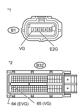 |
Disconnect the mass air flow meter connector.
Disconnect the ECM connector.
Measure the resistance according to the value(s) in the table below.
| Tester Connection | Condition | Specified Condition |
| B1-1 (VG) - B32-65 (VG) | Always | Below 1 Ω |
| B1-2 (E2G) - B32-64 (EVG) | Always | Below 1 Ω |
| Tester Connection | Condition | Specified Condition |
| B1-1 (VG) or B32-65 (VG) - Body ground | Always | 10 kΩ or higher |
| *1 | Front view of wire harness connector (to Mass Air Flow Meter) |
| *2 | Front view of wire harness connector (to ECM) |
Reconnect the mass air flow meter connector.
Reconnect the ECM connector.
|
| ||||
| OK | |
|
| 7.REPLACE ECM |
Replace the ECM (Click here).
|
| ||||
| 8.READ VALUE USING INTELLIGENT TESTER (MASS AIR FLOW RATE AND ENGINE SPEED) |
Connect the intelligent tester to the DLC3.
Turn the ignition switch to ON and turn the tester on.
Enter the following menus: Powertrain / Engine and ECT / Data List / MAF and Engine speed.
Read the value.
| Engine speed | MAF |
| 0 rpm | 0.03 g/s or less |
|
| ||||
| OK | |
|
| 9.READ VALUE USING INTELLIGENT TESTER (MAP AND ATMOSPHERIC PRESSURE) |
Connect the intelligent tester to the DLC3.
Turn the ignition switch to ON and turn the tester on.
Enter the following menus: Powertrain / Engine and ECT / Data List / MAP and Atmospheric Pressure.
Compare the values when the ignition switch is ON.
|
| ||||
| OK | |
|
| 10.INSPECT INTAKE AIR TEMPERATURE SENSOR |
Inspect the intake air temperature sensor (Click here).
|
| ||||
| OK | |
|
| 11.INSPECT EGR VALVE ASSEMBLY |
Connect the intelligent tester to the DLC3.
Turn the ignition switch to ON and turn the tester on.
Enter the following menus: Powertrain / Engine and ECT / Data List / EGR Close Lrn. Status.
Read the values.
Enter the following menus: Powertrain / Engine and ECT / Active Test / Control the EGR Step Position.
When changing the Active Test continuously value to 0, 30, 60, 90, 60, 30 and 0%, check that Actual EGR Valve Pos. smoothly changes to the set opening angle.
Remove the EGR valve assembly (Click here).
Visually check the electric EGR control valve for deposits.
If there are deposits, clean the electric EGR control valve.
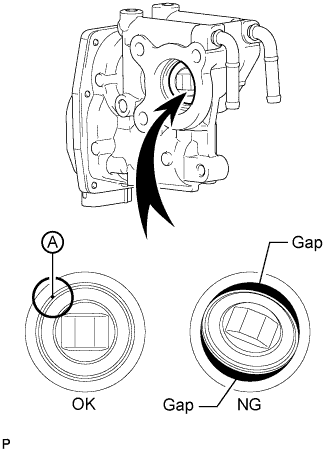 |
Hold the electric EGR control valve up to a light, and then from the side indicated by the arrow in the illustration, visually check that there is no gap between the valve and body.
|
| ||||
| OK | |
|
| 12.CHECK AIR INDUCTION SYSTEM |
Check the air induction system for vacuum leakage .
|
| ||||
| OK | |
|
| 13.CHECK HARNESS AND CONNECTOR (MASS AIR FLOW METER - ECM) |
|
Disconnect the mass air flow meter connector.
Disconnect the ECM connector.
Measure the resistance according to the value(s) in the table below.
| Tester Connection | Condition | Specified Condition |
| B1-1 (VG) - B32-65 (VG) | Always | Below 1 Ω |
| B1-2 (E2G) - B32-64 (EVG) | Always | Below 1 Ω |
| Tester Connection | Condition | Specified Condition |
| B1-1 (VG) or B32-65 (VG) - Body ground | Always | 10 kΩ or higher |
| *1 | Front view of wire harness connector (to Mass Air Flow Meter) |
| *2 | Front view of wire harness connector (to ECM) |
Reconnect the mass air flow meter connector.
Reconnect the ECM connector.
|
| ||||
| OK | |
|
| 14.REPLACE MASS AIR FLOW METER |
Replace the mass air flow meter (Click here).
| NEXT | |
|
| 15.CHECK DTC OUTPUT |
Connect the intelligent tester to the DLC3.
Clear the DTCs (Click here).
Turn the ignition switch off for 30 seconds or more.
Start the engine.
After the engine is completely warmed up, perform the following procedure 3 times with the A/C off: from a vehicle speed of 60 km/h (37 mph), accelerate the vehicle to 80 km/h (50 mph), quickly release the accelerator pedal and do not depress it for 7 seconds or more.
Stop the vehicle immediately after completing the above procedure.
Connect the intelligent tester to the DLC3.
Enter the following menus: Powertrain / Engine and ECT / Data List / Exhaust Temperature B1S1.
Enter the following menus: Powertrain / Engine and ECT / DTC.
Read the pending DTCs.
Enter the following menus: Powertrain / Engine and ECT / Utility / All Readiness.
Input DTC P0101.
Check the DTC judgment result.
| Tester Display | Result | Proceed to |
| Pending DTC | P0101 is output | B |
| All Readiness | NORMAL | A |
| ABNORMAL | B |
|
| ||||
| A | ||
 | ||
| ||
| 16.REPAIR OR REPLACE AIR INDUCTION SYSTEM |
Repair or replace the air induction system.
|
| ||||
| 17.REPLACE EGR VALVE ASSEMBLY |
Replace the EGR valve assembly (Click here).
|
| ||||
| 18.REPLACE ECM |
Replace the ECM (Click here).
|
| ||||
| 19.REPLACE MANIFOLD ABSOLUTE PRESSURE SENSOR |
Replace the manifold absolute pressure sensor.
|
| ||||
| 20.REPLACE INTAKE AIR TEMPERATURE SENSOR |
Replace the intake air temperature sensor (Click here).
|
| ||||
| 21.REPAIR OR REPLACE HARNESS OR CONNECTOR |
Repair or replace the harness or connector.
| NEXT | |
|
| 22.CONFIRM WHETHER MALFUNCTION HAS BEEN SUCCESSFULLY REPAIRED |
Connect the intelligent tester to the DLC3.
Clear the DTCs (Click here).
Turn the ignition switch off for 30 seconds or more.
Start the engine.
After the engine is completely warmed up, perform the following procedure 3 times with the A/C off: from a vehicle speed of 60 km/h (37 mph), accelerate the vehicle to 80 km/h (50 mph), quickly release the accelerator pedal and do not depress it for 7 seconds or more.
Stop the vehicle immediately after completing the above procedure.
Connect the intelligent tester to the DLC3.
Enter the following menus: Powertrain / Engine and ECT / Data List / Exhaust Temperature B1S1.
Enter the following menus: Powertrain / Engine and ECT / DTC.
Confirm that the pending DTC is not output again.
Enter the following menus: Powertrain / Engine and ECT / Utility / All Readiness.
Input DTC P0101.
Check the DTC judgment result.
| NEXT | ||
| ||
| ||
