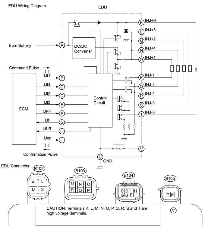
DTC P062D Fuel Injector Driver Circuit Performance Bank1 |
| DTC Detection Drive Pattern | DTC Detection Condition | Trouble Area |
| Idling for 5 seconds | Open or short in the injector driver (EDU) or fuel injector circuit. (1 trip detection logic) |
|
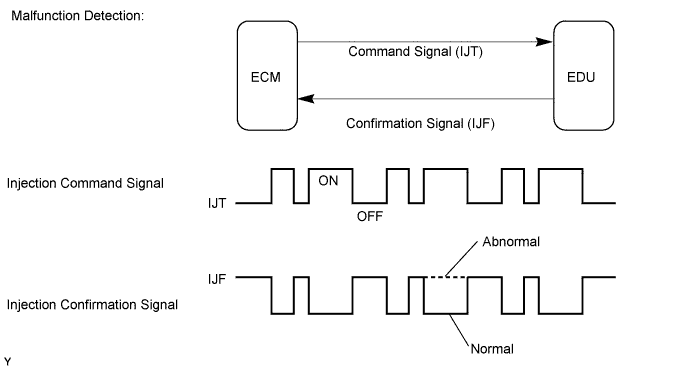
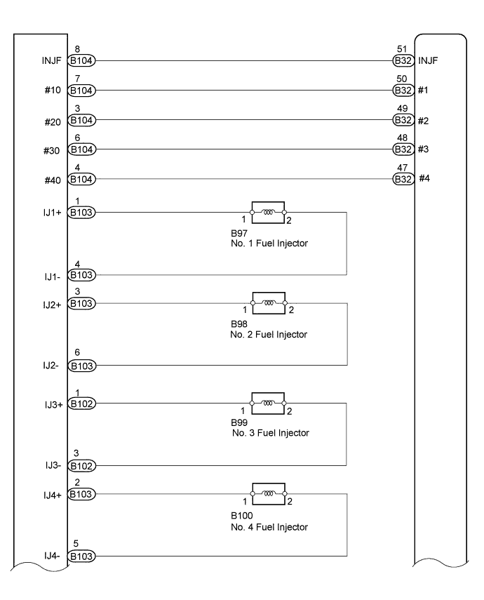
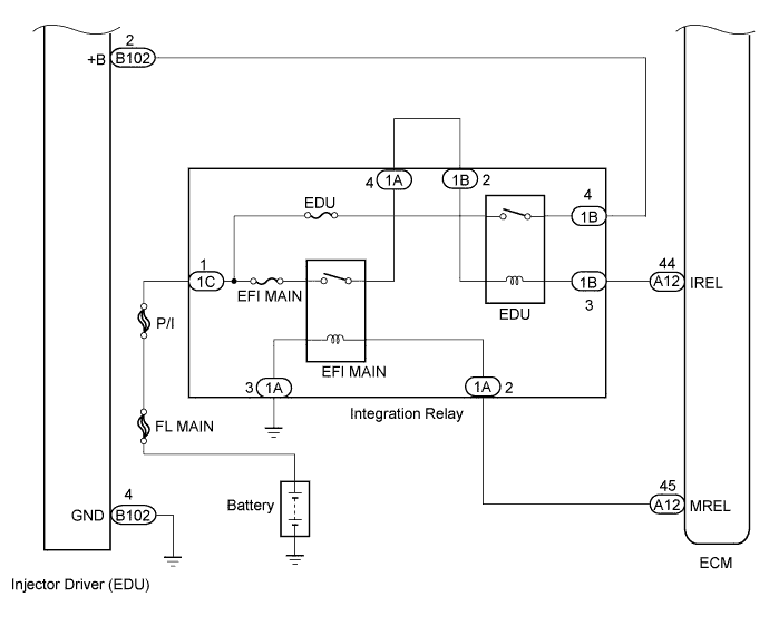
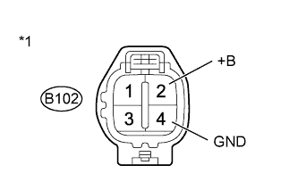
| 1.CHECK TERMINAL VOLTAGE EDU POWER SOURCE |
 |
Disconnect the injector driver (EDU) connector.
Measure the voltage according to the value(s) in the table below.
| Tester Connection | Switch Condition | Specified Condition |
| B102-2 (+B) - B102-4 (GND) | Ignition switch ON | 11 to 14 V |
| *1 | Front view of wire harness connector (to Injector Driver (EDU)) |
Reconnect the injector driver (EDU) connector.
|
| ||||
| OK | |
 |
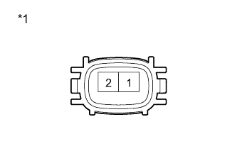
| 2.INSPECT FUEL INJECTOR (RESISTANCE) |
 |
Disconnect the fuel injector connectors.
Measure the resistance according to the value(s) in the table below.
| Tester Connection | Condition | Specified Condition |
| 1 - 2 | 20°C (68°F) | 0.85 to 1.05 Ω |
| *1 | Component without harness connected (Injector) |
Reconnect the fuel injector connectors.
|
| ||||
| OK | |
|
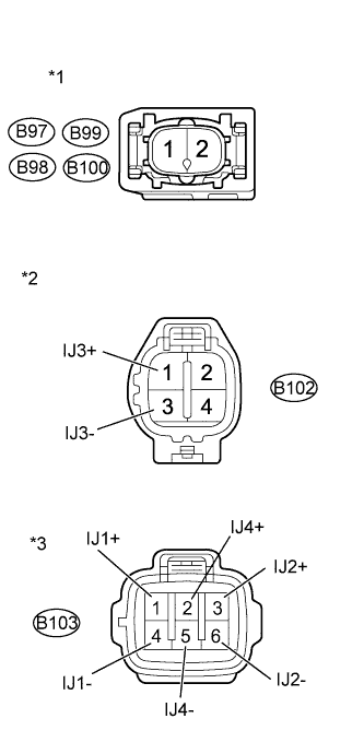
| 3.CHECK HARNESS AND CONNECTOR (FUEL INJECTOR - EDU) |
 |
Disconnect the fuel injector connectors.
Disconnect the EDU connectors.
Measure the resistance according to the value(s) in the table below.
| Tester Connection | Condition | Specified Condition |
| B97-1 - B103-1 (IJ1+) | Always | Below 1 Ω |
| B97-2 - B103-4 (IJ1-) | Always | Below 1 Ω |
| B98-1 - B103-3 (IJ2+) | Always | Below 1 Ω |
| B98-2 - B103-6 (IJ2-) | Always | Below 1 Ω |
| B99-1 - B102-1 (IJ3+) | Always | Below 1 Ω |
| B99-2 - B102-3 (IJ3-) | Always | Below 1 Ω |
| B100-1 - B103-2 (IJ4+) | Always | Below 1 Ω |
| B100-2 - B103-5 (IJ4-) | Always | Below 1 Ω |
| Tester Connection | Condition | Specified Condition |
| B97-1 or B103-1 (IJ1+) - Body ground | Always | 10 kΩ or higher |
| B97-2 or B103-4 (IJ1-) - Body ground | Always | 10 kΩ or higher |
| B98-1 or B103-3 (IJ2+) - Body ground | Always | 10 kΩ or higher |
| B98-2 or B103-6 (IJ2-) - Body ground | Always | 10 kΩ or higher |
| B99-1 or B102-1 (IJ3+) - Body ground | Always | 10 kΩ or higher |
| B99-2 or B102-3 (IJ3-) - Body ground | Always | 10 kΩ or higher |
| B100-1 or B103-2 (IJ4+) - Body ground | Always | 10 kΩ or higher |
| B100-2 or B103-5 (IJ4-) - Body ground | Always | 10 kΩ or higher |
| *1 | Front view of wire harness connector (to Injector) |
| *2 | Front view of wire harness connector (to Injector Driver (EDU)) |
| *3 | Front view of wire harness connector (to Injector Driver (EDU)) |
Reconnect the fuel injector connectors.
Reconnect the EDU connectors.
|
| ||||
| OK | |
|
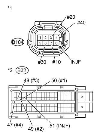
| 4.CHECK HARNESS AND CONNECTOR (EDU - ECM) |
 |
Disconnect the EDU connector.
Disconnect the ECM connector.
Measure the resistance according to the value(s) in the table below.
| Tester Connection | Condition | Specified Condition |
| B104-7 (#10) - B32-50 (#1) | Always | Below 1 Ω |
| B104-3 (#20) - B32-49 (#2) | Always | Below 1 Ω |
| B104-6 (#30) - B32-48 (#3) | Always | Below 1 Ω |
| B104-4 (#40) - B32-47 (#4) | Always | Below 1 Ω |
| B104-8 (INJF) - B32-51 (INJF) | Always | Below 1 Ω |
| Tester Connection | Condition | Specified Condition |
| B104-7 (#10) or B32-50 (#1) - Body ground | Always | 10 kΩ or higher |
| B104-3 (#20) or B32-49 (#2) - Body ground | Always | 10 kΩ or higher |
| B104-6 (#30) or B32-48 (#3) - Body ground | Always | 10 kΩ or higher |
| B104-4 (#40) or B32-47 (#4) - Body ground | Always | 10 kΩ or higher |
| B104-8 (INJF) or B32-51 (INJF) - Body ground | Always | 10 kΩ or higher |
| *1 | Front view of wire harness connector (to Injector Driver (EDU)) |
| *2 | Front view of wire harness connector (to ECM) |
Reconnect the EDU connector.
Reconnect the ECM connector.
|
| ||||
| OK | |
|
| 5.REPLACE EDU |
Replace the EDU (Click here).
| NEXT | |
|
| 6.CHECK WHETHER DTC OUTPUT RECURS |
Connect the intelligent tester to the DLC3.
Clear the DTCs (Click here).
Turn the ignition switch off for 30 seconds or more.
Start the engine and idle it for 10 seconds.
Enter the following menus: Powertrain / Engine and ECT / DTC.
Read the DTCs.
| Result | Proceed to |
| P062D is output | A |
| No output | B |
|
| ||||
| A | |
|
| 7.REPLACE ECM |
Replace the ECM (Click here).
|
| ||||
| 8.GO TO INJECTOR CIRCUIT |
Go to the injector circuit (Click here).
|
| ||||
| 9.REPLACE FUEL INJECTOR |
Replace the fuel injector (Click here).
| NEXT | |
|
| 10.BLEED AIR FROM FUEL SYSTEM |
Bleed the air from the fuel system .
| NEXT | |
|
| 11.REGISTER INJECTOR COMPENSATION CODE AND PERFORM PILOT QUANTITY LEARNING |
Register the injector compensation code .
Perform the fuel injector pilot quantity learning .
|
| ||||
| 12.REPAIR OR REPLACE HARNESS OR CONNECTOR |
Repair or replace the harness or connector.
| NEXT | |
|
| 13.CONFIRM WHETHER MALFUNCTION HAS BEEN SUCCESSFULLY REPAIRED |
Connect the intelligent tester to the DLC3.
Clear the DTCs (Click here).
Turn the ignition switch off for 30 seconds or more.
Start the engine and idle it for 10 seconds.
Enter the following menus: Powertrain / Engine and ECT / DTC.
Confirm that the DTC is not output again.
| NEXT | ||
 | ||
| ||

