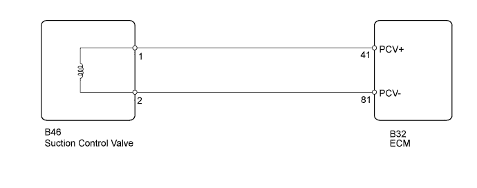
DTC P0627 Fuel Pump Control Circuit / Open |
| DTC Detection Drive Pattern | DTC Detection Condition | Trouble Area |
| Idling for 1 second | Even though the CPU (command area inside ECU) is outputting the suction control valve operation duty, the output monitor signal is absent for 0.5 seconds. (1 trip detection logic) |
|
| DTC No. | Data List |
| P0627 | Fuel Press Target Common Rail Pressure |
| 1.INSPECT FUEL SUPPLY PUMP (SUCTION CONTROL VALVE) |
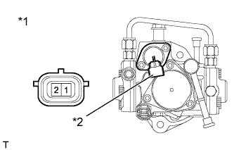 |
Disconnect the suction control valve connector.
Measure the resistance according to the value(s) in the table below.
| Tester Connection | Condition | Specified Condition |
| 1 - 2 | 20°C (68°F) | 1.9 to 2.3 Ω |
| *1 | Fuel Supply Pump |
| *2 | Component without harness connected (Suction Control Valve) |
Reconnect the suction control valve connector.
|
| ||||
| OK | |
 |
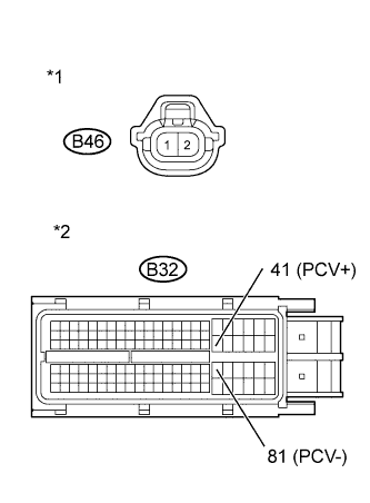
| 2.CHECK HARNESS AND CONNECTOR (SUCTION CONTROL VALVE - ECM) |
 |
Disconnect the suction control valve connector.
Disconnect the ECM connector.
Measure the resistance according to the value(s) in the table below.
| Tester Connection | Condition | Specified Condition |
| B46-1 (+B) - B32-41 (PCV+) | Always | Below 1 Ω |
| B46-2 (PCV) - B32-81 (PCV-) | Always | Below 1 Ω |
| Tester Connection | Condition | Specified Condition |
| B46-1 (+B) or B32-41 (PCV+) - Body ground | Always | 10 kΩ or higher |
| B46-2 (PCV) or B32-81 (PCV-) - Body ground | Always | 10 kΩ or higher |
| *1 | Front view of wire harness connector (to Suction Control Valve) |
| *2 | Front view of wire harness connector (to ECM) |
Reconnect the suction control valve connector.
Reconnect the ECM connector.
|
| ||||
| OK | |
|
| 3.CHECK WHETHER DTC OUTPUT RECURS |
Connect the intelligent tester to the DLC3
Turn the ignition switch to ON and turn the tester on.
Clear the DTCs (Click here).
Start the engine and idle it for 1 second or more.
Enter the following menus: Powertrain / Engine and ECT / DTC.
Read the DTCs.
| Result | Proceed to |
| No DTC is output | A |
| P0627 is output | B |
|
| ||||
| A | ||
 | ||
| ||
| 4.REPLACE FUEL SUPPLY PUMP |
Replace the fuel supply pump (Click here).
| NEXT | |
|
| 5.BLEED AIR FROM FUEL SYSTEM |
Bleed the air from the fuel system .
| NEXT | |
|
| 6.PERFORM FUEL SUPPLY PUMP INITIALIZATION |
Perform fuel supply pump initialization (Click here).
|
| ||||
| 7.REPLACE ECM |
Replace the ECM (Click here).
|
| ||||
| 8.REPAIR OR REPLACE HARNESS OR CONNECTOR |
Repair or replace the harness or connector.
| NEXT | |
|
| 9.CONFIRM WHETHER MALFUNCTION HAS BEEN SUCCESSFULLY REPAIRED |
Connect the intelligent tester to the DLC3.
Clear the DTCs (Click here).
Turn the ignition switch off for 30 seconds or more.
Start the engine and idle it for 1 second or more.
Confirm that the DTC is not output again.
| NEXT | ||
| ||
| ||
