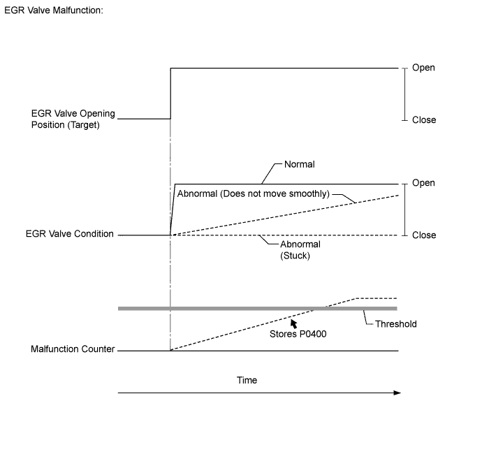
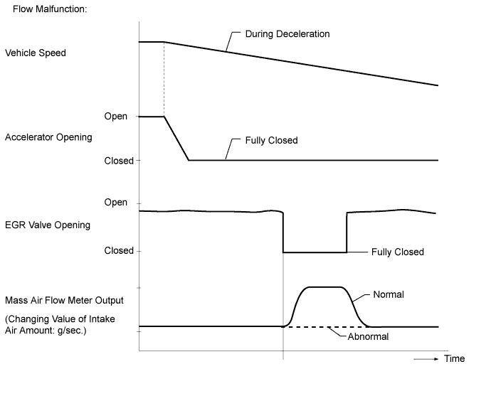
DTC P0400 Exhaust Gas Recirculation Flow |
| DTC Detection Drive Pattern | DTC Detection Condition | Trouble Area |
| After warming up engine and idling for 60 seconds, maintain engine speed at 2500 rpm for 40 seconds, drive vehicle, and perform engine brake deceleration by fully closing accelerator when engine speed is 2000 rpm or more. | The target and actual positions of the EGR valve are different for 40 seconds or more. (1 trip detection logic) |
|
| DTC Detection Drive Pattern | DTC Detection Condition | Trouble Area |
After warming up the engine, decelerate from a speed of 80 km/h (50 mph) or more (fully release the accelerator pedal for approximately 5 seconds).
| Mass air flow rate is not changed when turning on the electric EGR control valve while decelerating. (2 trip detection logic) |
|
| DTC No. | Data List |
| P0400 (EGR valve malfunction) P0400 (Flow malfunction) |
|
| 1.CHECK ANY OTHER DTCS OUTPUT (IN ADDITION TO DTC P0400) |
Connect the intelligent tester to the DLC3.
Turn the ignition switch to ON and turn the tester on.
Enter the following menus: Powertrain / Engine and ECT / DTC.
Read Current DTCs.
| Result | Proceed to |
| P0400 | A |
| P0400 and other DTCs output | B |
|
| ||||
| A | |
 |
| 2.CHECK FREEZE FRAME DATA (TARGET EGR POS. AND ACTUAL EGR VALVE POS.) |
Connect the intelligent tester to the DLC3.
Turn the ignition switch to ON and turn the tester on.
Enter the following menus: Powertrain / Engine and ECT / DTC.
Read the values of Target EGR Position and Actual EGR Valve Pos. in Freeze Frame Data.
|
| ||||
|
| ||||
| 3.CHECK FOR EXHAUST GAS LEAKS |
Check for exhaust gas leaks.
| Result | Proceed to |
| Exhaust gas leaks out from exhaust system | A |
| No leaks | B |
|
| ||||
| A | |
|
| 4.REPAIR EXHAUST GAS LEAK |
Repair or replace the malfunctioning part in the exhaust system.
| NEXT | |
|
| 5.CHECK AIR INTAKE SYSTEM (AIR LEAKS AND BLOCKAGES) |
Check for air leaks and blockages in the air intake system.
| Result | Proceed to |
| Leaks or blockages exist in the air intake system | A |
| No leaks and blockages in the intake system | B |
|
| ||||
| A | |
|
| 6.REPAIR OR REPLACE AIR INTAKE SYSTEM |
Repair or replace the malfunctioning part in the air intake system.
| NEXT | |
|
| 7.INSPECT EGR VALVE ASSEMBLY |
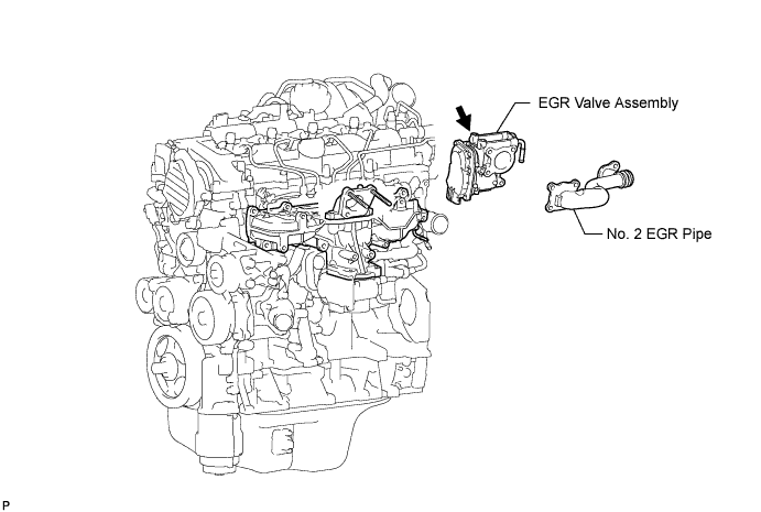
Remove the EGR valve assembly.
Visually check the electric EGR control valve for deposits.
If there are deposits, clean the electric EGR control valve.
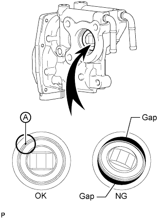 |
Hold the electric EGR control valve up to a light, and then from the side indicated by the arrow in the illustration, visually check that there is no gap between the valve and body.
|
| ||||
|
| ||||
| 8.INSPECT EGR VALVE ASSEMBLY |
Remove the EGR valve assembly.
Visually check the electric EGR control valve for deposits.
If there are deposits, clean the electric EGR control valve.
|
Hold the electric EGR control valve up to a light, and then from the side indicated by the arrow in the illustration, visually check that there is no gap between the valve and body.
|
| ||||
|
| ||||
| 9.REPLACE EGR VALVE ASSEMBLY |
Replace the EGR valve assembly (Click here).
| NEXT | |
|
| 10.CHECK EGR VALVE ASSEMBLY |
With the EGR valve assembly removed from the vehicle, connect the EGR valve connector.
Connect the intelligent tester to the DLC3.
Turn the ignition switch to ON and turn the tester on.
Enter the following menus: Powertrain / Engine and ECT / Active Test / Control the EGR Step Position / Diesel EGR / Target EGR Pos. and Actual EGR Valve Pos..
Check that the EGR valve assembly operates.
|
| ||||
|
| ||||
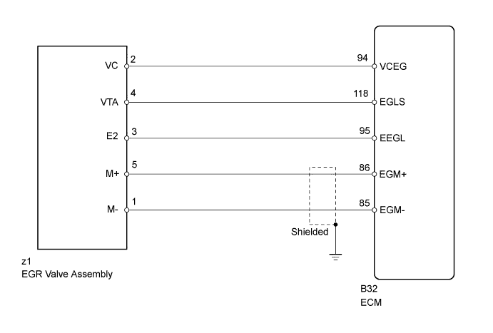
| 11.CHECK HARNESS AND CONNECTOR (EGR VALVE - ECM) |
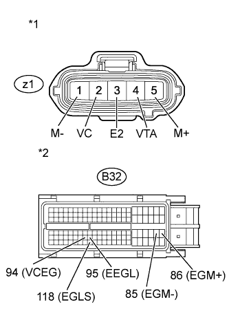 |
Disconnect the EGR valve assembly connector.
Disconnect the ECM connector.
Measure the resistance according to the value(s) in the table below.
| Tester Connection | Condition | Specified Condition |
| z1-5 (M+) - B32-86 (EGM+) | Always | Below 1 Ω |
| z1-1 (M-) - B32-85 (EGM-) | Always | Below 1 Ω |
| z1-2 (VC) - B32-94 (VCEG) | Always | Below 1 Ω |
| z1-4 (VTA) - B32-118 (EGLS) | Always | Below 1 Ω |
| z1-3 (E2) - B32-95 (EEGL) | Always | Below 1 Ω |
| Tester Connection | Condition | Specified Condition |
| z1-5 (M+) or B32-86 (EGM+) - Body ground | Always | 10 kΩ or higher |
| z1-2 (VC) or B32-94 (VCEG) - Body ground | Always | 10 kΩ or higher |
| z1-4 (VTA) or B32-118 (EGLS) - Body ground | Always | 10 kΩ or higher |
| *1 | Front view of wire harness connector (to Electric EGR Valve Assembly) |
| *2 | Front view of wire harness connector (to ECM) |
Reconnect the EGR valve assembly connector.
Reconnect the ECM connector.
|
| ||||
| OK | |
|
| 12.REPLACE EGR VALVE ASSEMBLY |
Replace the EGR valve assembly (Click here).
|
| ||||
| 13.REPAIR OR REPLACE HARNESS OR CONNECTOR |
Repair or replace any malfunctioning harnesses or connectors.
| NEXT | |
|
| 14.CHECK FOR DEPOSIT (EGR PASSAGE) |
Check the deposit conditions in the EGR valve assembly.
| Result | Proceed to |
| Wet carbon exists | A |
| Dry carbon exists | B |
|
| ||||
| A | |
|
| 15.REPLACE EGR VALVE ASSEMBLY |
Replace the EGR valve assembly (Click here).
|
| ||||
| 16.REMOVE DEPOSIT (CLEAN EGR PASSAGE) |
Remove the intake manifold, No. 2 intake manifold, EGR valve assembly and No. 2 EGR pipe.
Remove the deposits from those parts and clean the parts.
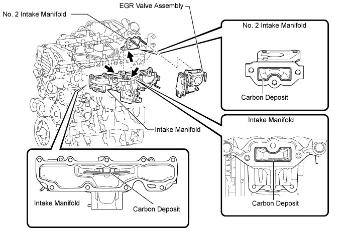
Reinstall the intake manifold, No. 2 intake manifold, EGR valve assembly and No. 2 EGR pipe.
| NEXT | |
|
| 17.CHECK FOR CAUSE OF FAILURE |
Start the engine and warm it up.
Turn the ignition switch off for 30 seconds or more.
Connect the intelligent tester to the DLC3.
Read the values of the Data List items when the engine is under the following conditions.
Ignition switch ON (engine not running).
Idling (after 1 minute or more elapsed).
Engine maintained at 4500 rpm with no load.
Take snapshots with the intelligent tester for each engine condition above and analyze the cause of black smoke emission by referring to the table below.
| Engine Condition | Data List Item | Standard | Diagnostic Note |
| Ignition switch ON | MAP | Difference between MAP and Atmosphere Pressure is +/-8 kPa | If the difference exceeds the standard range, the sensor that indicates the value most different from the actual atmospheric pressure is malfunctioning. |
| Atmosphere Pressure | |||
| Injector Compensation Code*1 | The injector compensation codes stored in the ECM match the injector compensation codes of the installed fuel injectors. | If the codes do not match, input the correct codes by referring to "Registration". | |
| Idling | Injection Feedback Val #1 Injection Feedback Val #2 Injection Feedback Val #3 Injection Feedback Val #4 | -3.0 to 3.0 mm3/st | The injector for which the value is out of the standard range is malfunctioning. |
| Injection Volume | Less than 10 mm3/st | If the value of Injection Volume is 10 mm3/st or more and the values of all Injector Feedback Val. (#1 to #4) are within the standard range, replace the fuel injectors for all cylinders. | |
| Coolant Temp |
| If the value is out of the standard range, check the engine coolant temperature sensor circuit. | |
| 4500 rpm with no load | MAP Target Booster Pressure | Difference between MAP and Target Booster Pressure is +/-15 kPa or less | - |
| Corrected MAF Value (for Manual Transaxle)*2 | 92 to 132 g/sec. When the following conditions are met:
| If the value is out of the standard range, check the following items.
| |
| Corrected MAF Value (for Automatic Transaxle)*3 | 90 to 135 g/sec. When the following conditions are met:
|
Check the vacuum hose connection (manifold absolute pressure sensor).
Check for air leaks in the intake pipes and hoses between the turbocharger and intake manifold.
Check for air leaks in the intake manifold.
Check for deposit in the EGR cooler.
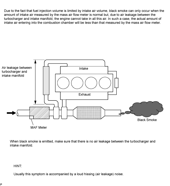
Check the turbocharger sub-assembly.
| NEXT | |
|
| 18.CHECK WHETHER DTC OUTPUT RECURS (DTC P0400) |
Connect the intelligent tester to the DLC3.
Turn the ignition switch to ON and turn the tester on.
Clear DTCs (Click here).
Turn the ignition switch off for 30 seconds or more.
Start the engine and warm it up.
Drive the vehicle with a stop-and-go city drive pattern for more than 10 minutes.
Decelerate from a speed of 80 km/h (50 mph) or more (fully closing the accelerator for approximately 5 seconds or more).
Enter the following menus: Powertrain / Engine and ECT / Utility / All Readiness.
Input DTC P0400.
Check the DTC judgment result.
| Result | Proceed to |
| ABNORMAL | A |
| NORMAL | B |
|
| ||||
| A | |
|
| 19.REPLACE EGR VALVE ASSEMBLY |
Replace the EGR valve assembly (Click here).
| NEXT | |
|
| 20.CHECK WHETHER DTC OUTPUT RECURS (DTC P0400) |
Connect the intelligent tester to the DLC3.
Turn the ignition switch to ON and turn the tester on.
Clear DTCs (Click here).
Turn the ignition switch off for 30 seconds or more.
Start the engine and warm it up.
Drive the vehicle with a stop-and-go city drive pattern for more than 10 minutes.
Decelerate from a speed of 80 km/h (50 mph) or more (fully closing the accelerator for approximately 5 seconds or more).
Enter the following menus: Powertrain / Engine and ECT / Utility / All Readiness.
Input DTC P0400.
Check the DTC judgment result.
| Result | Proceed to |
| ABNORMAL | A |
| NORMAL | B |
|
| ||||
| A | |
|
| 21.REPLACE ECM |
Replace the ECM (Click here).
| NEXT | |
|
| 22.CHECK WHETHER DTC OUTPUT RECURS (DTC P0400) |
Turn the ignition switch to ON.
Turn the ignition switch off, and wait for 30 seconds or more.
Connect the intelligent tester to the DLC3.
Turn the ignition switch to ON and turn the tester on.
Clear DTCs (Click here).
Start the engine and warm it up.
Drive the vehicle with a stop-and-go city drive pattern for more than 10 minutes.
Decelerate from a speed of 80 km/h (50 mph) or more (fully closing the accelerator for approximately 5 seconds or more).
Enter the following menus: Powertrain / Engine and ECT / DTC.
Confirm that the DTC is not output again.
Enter the following menus: Powertrain / Engine and ECT / Utility / All Readiness.
Input DTC P0400.
Check the DTC judgment result.
| NEXT | ||
 | ||
| ||

