ENGINE ASSEMBLY > REMOVAL |
| 1. DISCHARGE REFRIGERANT FROM REFRIGERATION SYSTEM |
Start the engine.
Turn the A/C switch on.
Operate the cooler compressor while the engine speed is approximately 1000 rpm for 5 to 6 minutes to circulate the refrigerant and collect the compressor oil remaining in each component into the cooler compressor.
Stop the engine.
Recover the refrigerant from the A/C system using a refrigerant recovery unit.
| 2. PLACE FRONT WHEELS FACING STRAIGHT AHEAD |
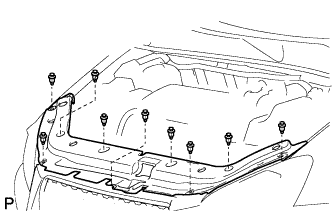
| 3. REMOVE RADIATOR SUPPORT OPENING COVER |
|
Remove the 9 clips and radiator support opening cover.
| 4. DISCONNECT CABLE FROM NEGATIVE BATTERY TERMINAL |
| 5. DISCONNECT CABLE FROM POSITIVE BATTERY TERMINAL |
| 6. REMOVE FRONT WHEEL |
| 7. REMOVE NO. 1 ENGINE COVER |
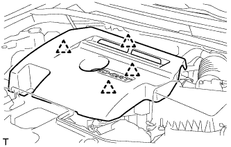 |
Detach the 4 clips and remove the engine cover.
| 8. REMOVE NO. 1 ENGINE UNDER COVER |
Remove the 6 bolts, 10 clips and engine under cover.
| 9. REMOVE NO. 2 ENGINE UNDER COVER |
Remove the 2 clips and engine under cover.
| 10. REMOVE REAR ENGINE UNDER COVER RH |
Remove the 2 clips and under cover.
| 11. REMOVE REAR ENGINE UNDER COVER LH |
Remove the 2 clips and under cover.
| 12. REMOVE FRONT FLOOR COVER |
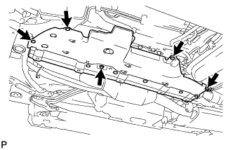 |
Remove the nut, bolt and clip, and then detach the 2 clips and remove the floor cover.
| 13. DRAIN ENGINE COOLANT |
Loosen the radiator drain cock plug.
Remove the radiator reservoir cap.
Loosen the cylinder block drain cock plug.
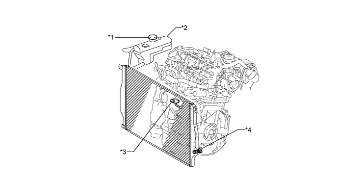
| *1 | Radiator Reservoir Cap | *2 | Radiator Reservoir |
| *3 | Cylinder Block Drain Cock | *4 | Radiator Drain Cock Plug |
| 14. DRAIN ENGINE OIL |
Remove the oil filler cap.
Remove the clip and open the oil pan drain service cover.
Remove the oil pan drain plug and gasket, and then drain the engine oil into a container.
Install a new gasket and the oil pan drain plug.
Close the oil pan drain service cover and install the clip
| 15. DRAIN MANUAL TRANSAXLE OIL (for Manual Transaxle) |
Remove the filler plug and gasket.
Remove the drain plug and gasket, and drain the oil.
Install a new gasket and the drain plug.
| 16. DRAIN AUTOMATIC TRANSAXLE FLUID (for Automatic Transaxle) |
Remove the refill plug and gasket from the automatic transaxle.
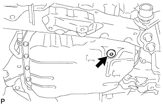 |
Using a 6 mm socket hexagon wrench, remove the overflow plug and gasket from the automatic transaxle.
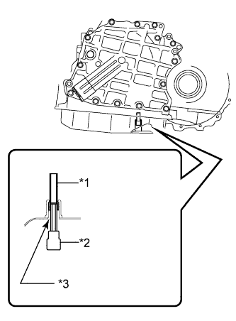 |
Using a 6 mm socket hexagon wrench, remove the No. 1 transmission oil filler tube from the automatic transaxle and drain the automatic transaxle fluid.
Using a 6 mm socket hexagon wrench, install the No. 1 transmission oil filler tube to the automatic transaxle.
| *1 | No. 1 Transmission Oil Filler Tube |
| *2 | Hexagon Socket Wrench |
| *3 | Overflow Plug Hole |
Using a 6 mm socket hexagon wrench, install a new gasket and the overflow plug to the automatic transaxle.
Temporarily install the gasket and the refill plug to the automatic transaxle.
| 17. DRAIN TRANSFER OIL |
Remove the drain plug and gasket, and drain the oil.
Install a new gasket and the drain plug.
| 18. REMOVE FRONT EXHAUST PIPE ASSEMBLY |
Remove the front exhaust pipe (Click here).
| 19. REMOVE DIFFERENTIAL PRESSURE SENSOR ASSEMBLY |
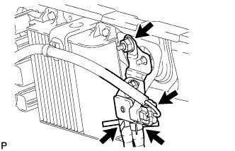 |
Disconnect the sensor connector.
Disconnect the 2 vacuum hoses.
Remove the nut and sensor.
| 20. REMOVE FRONT BUMPER COVER (for Automatic Transaxle) |
Remove the front bumper cover (Click here).
| 21. REMOVE BATTERY CLAMP SUB-ASSEMBLY |
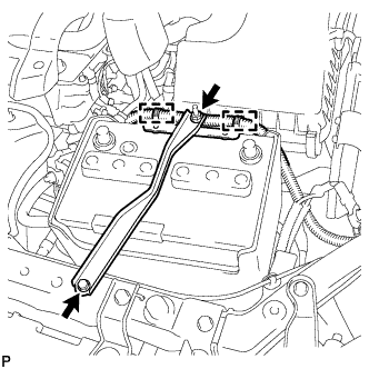 |
Remove the bolt and loosen the nut.
Detach the 2 wire harness clamps.
Detach the hook of the battery clamp from the front battery bracket, and then remove the battery clamp.
| 22. REMOVE BATTERY |
| 23. REMOVE BATTERY TRAY |
| 24. REMOVE FRONT BATTERY BRACKET |
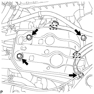 |
Detach the 2 wire harness clamps.
Remove the 4 bolts and front battery bracket.
| 25. REMOVE BATTERY BRACKET REINFORCEMENT |
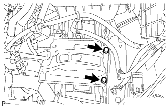 |
Remove the 2 bolts and battery bracket reinforcement.
| 26. REMOVE RADIATOR ASSEMBLY (for Automatic Transaxle) |
Remove the radiator (Click here).
| 27. DISCONNECT NO. 2 VACUUM TRANSMITTING HOSE ASSEMBLY |
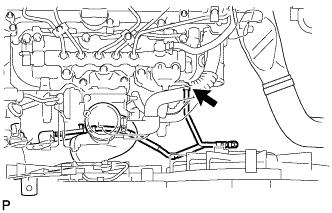 |
Disconnect the No. 2 vacuum transmitting hose from the intake manifold.
| 28. REMOVE NO. 3 AIR HOSE |
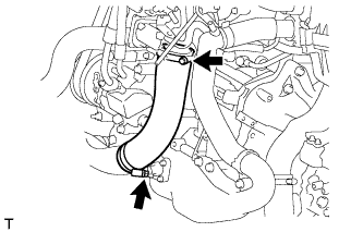 |
Loosen the 2 hose clamps.
Remove the No. 3 air hose from the No. 2 air tube and throttle body.
| 29. REMOVE AIR CLEANER CAP SUB-ASSEMBLY |
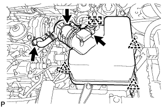 |
Detach the clamp and disconnect the mass air flow meter connector.
Disconnect the PCV hose.
Disconnect the air cleaner hose.
Detach the 3 clips and remove the air cleaner cap.
| 30. REMOVE AIR CLEANER FILTER ELEMENT SUB-ASSEMBLY |
| 31. REMOVE AIR CLEANER CASE |
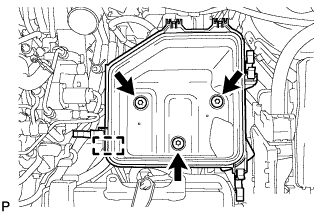 |
Detach the clamp.
Remove the 3 bolts and air cleaner case.
| 32. REMOVE FUEL FILTER ASSEMBLY |
Disconnect the level warning switch connector.
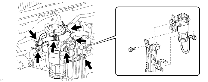
Disconnect the 4 hoses indicated in the illustration.
Remove the bolt and fuel filter.
| 33. REMOVE ECM |
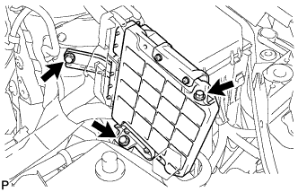 |
Remove the 3 bolts holding the ECM brackets.
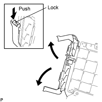 |
Raise the 2 levers while pushing the locks on the 2 levers, and disconnect the 2 ECM connectors.
Remove the ECM.
| 34. DISCONNECT HOSES AND CONNECTORS |
Remove the engine room No. 1 relay block cover.
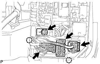 |
Disconnect the 3 connectors.
Remove the nut.
Detach the 2 claws and remove the engine room No. 1 relay block.
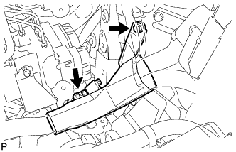 |
Remove the bolt and detach the engine wire cover clamp.
Remove the nut and disconnect the starter wire.
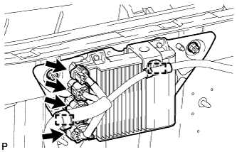 |
Detach the 2 clamps and disconnect the 4 EDU connectors.
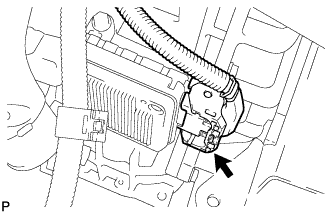 |
for Automatic Transaxle:
Disconnect the TCM connector.
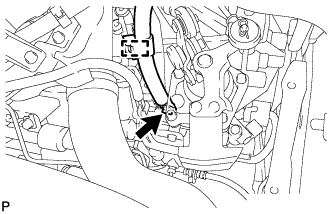 |
for Manual Transaxle:
Detach the clamp, remove the bolt and disconnect the ground cable.
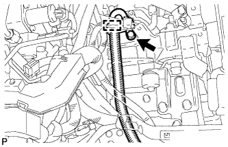 |
for Automatic Transaxle:
Detach the clamp, remove the bolt and disconnect the ground cable.
Disconnect the 2 fuel hoses.
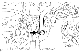 |
Disconnect the vacuum pump hose.
| 35. REMOVE AIR CLEANER SUPPORT |
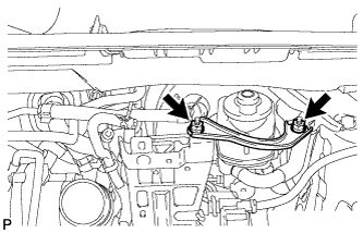 |
Remove the 2 nuts and air cleaner support.
| 36. REMOVE AIR CLEANER BRACKET |
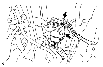 |
Disconnect the glow relay.
Disconnect the fuel filter level switch connector.
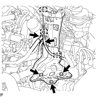 |
Detach the 3 wire harness clamps.
Disconnect the 2 fuel hoses from the bracket.
Remove the 3 bolts and bracket.
| 37. DISCONNECT INLET HEATER WATER HOSE |
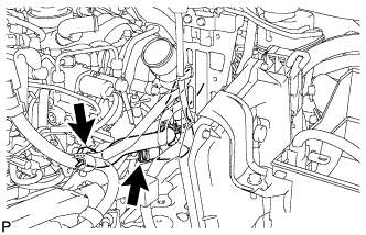 |
Disconnect the inlet heater water hose.
| 38. DISCONNECT OUTLET HEATER WATER HOSE |
Disconnect the outlet heater water hose.
| 39. DISCONNECT NO. 1 RADIATOR HOSE (for Manual Transaxle) |
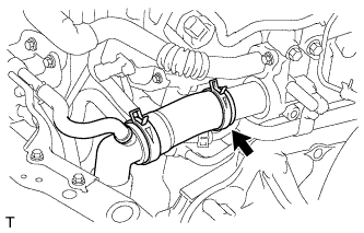 |
Disconnect the No. 1 radiator hose.
| 40. REMOVE INTERCOOLER AIR HOSE (for Manual Transaxle) |
Loosen the 2 clamps and remove the intercooler air hose.
| 41. DISCONNECT NO. 2 WATER BY-PASS HOSE |
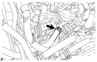 |
Disconnect the water by-pass hose.
| 42. DISCONNECT NO. 2 RADIATOR HOSE (for Manual Transaxle) |
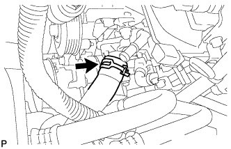 |
Disconnect the No. 2 radiator hose.
| 43. REMOVE RADIATOR RESERVOIR ASSEMBLY |
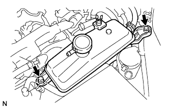 |
Remove the 2 bolts and reservoir.
| 44. DISCONNECT DISCHARGE HOSE SUB-ASSEMBLY |
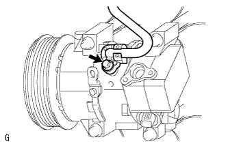 |
Remove the bolt and disconnect the cooler refrigerant discharge hose from the cooler compressor.
Remove the O-ring from the cooler refrigerant discharge hose.
| 45. DISCONNECT SUCTION HOSE SUB-ASSEMBLY |
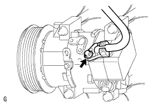 |
Remove the bolt and disconnect the cooler refrigerant suction hose from the cooler compressor.
Remove the O-ring from the cooler refrigerant suction hose.
| 46. DISCONNECT TRANSMISSION CONTROL CABLE ASSEMBLY (for Manual Transaxle) |
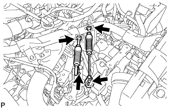 |
Remove the 2 pins and disconnect the 2 cables from the transaxle.
Remove the 2 clips and disconnect the 2 cables from the control cable bracket.
| 47. DISCONNECT TRANSMISSION CONTROL CABLE ASSEMBLY (for Automatic Transaxle) |
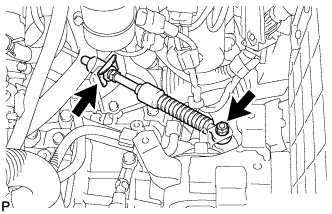 |
Remove the nut and clip, and disconnect the transmission control cable.
| 48. DISCONNECT CLUTCH RELEASE CYLINDER ASSEMBLY (for Manual Transaxle) |
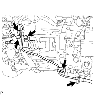 |
Remove the clip and 4 bolts and disconnect the release cylinder and flexible hose bracket.
| 49. REMOVE PROPELLER WITH CENTER BEARING SHAFT ASSEMBLY |
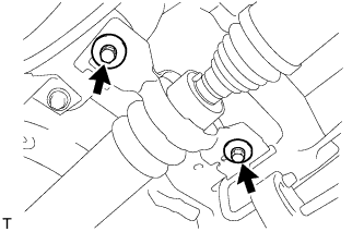 |
Remove the 2 bolts and 2 adjusting washers, and disconnect the propeller with center bearing shaft.
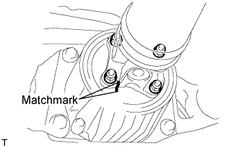 |
Place matchmarks on the differential carrier and propeller shaft.
Remove the 4 nuts and 4 washers, and disconnect the propeller shaft and differential carrier.
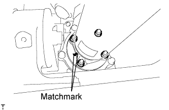 |
Place matchmarks on the transfer and propeller shaft.
Remove the 4 nuts and 4 washers, and disconnect the propeller shaft from the transfer.
| 50. REMOVE COLUMN HOLE COVER SILENCER SHEET |
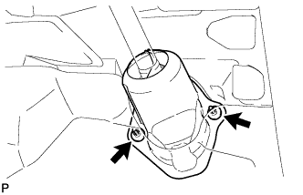 |
Turn back the floor carpet and remove the 2 clips and silencer sheet.
| 51. DISCONNECT STEERING INTERMEDIATE SHAFT |
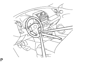 |
Use a seat belt to fix the steering wheel in place to avoid breakage of the spiral cable.
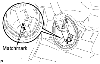 |
Place matchmarks on the sliding yoke of the No. 2 steering intermediate shaft.
Remove the bolt and disconnect the sliding yoke.
| 52. REMOVE NO. 1 STEERING COLUMN HOLE COVER SUB-ASSEMBLY |
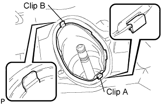 |
Remove the clip A, detach the clip B from the body and disconnect the No. 1 steering column hole cover.
| 53. DISCONNECT FRONT SPEED SENSOR LH |
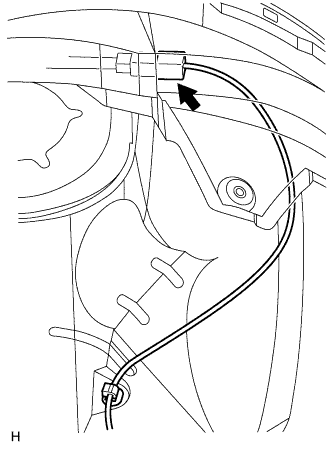 |
Disconnect the sensor connector.
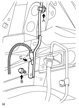 |
Remove the sensor clip (labeled A), bolt (labeled B) and sensor clamp (labeled C).
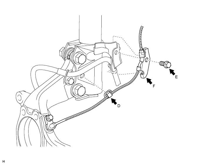
Remove the sensor clip (labeled D), bolt (labeled E) and sensor clamp (labeled F).
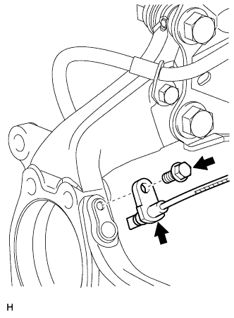 |
Remove the bolt and sensor body from the knuckle.
| 54. DISCONNECT FRONT SPEED SENSOR RH |
| 55. REMOVE FRONT AXLE SHAFT NUT LH |
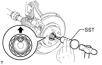 |
Using SST and a hammer, unstake the staked part of the nut.
While applying the brakes, remove the lock axle hub nut.
| 56. REMOVE FRONT AXLE SHAFT NUT RH |
| 57. DISCONNECT FRONT STABILIZER LINK ASSEMBLY LH |
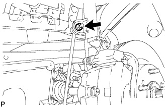 |
Remove the nut and disconnect the front stabilizer link.
| 58. DISCONNECT FRONT STABILIZER LINK ASSEMBLY RH |
| 59. REMOVE FRONT SUSPENSION NO. 1 LOWER ARM SUB-ASSEMBLY LH |
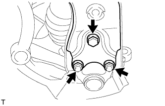 |
Remove the 2 nuts and bolt, and disconnect the lower arm from the ball joint.
| 60. REMOVE FRONT SUSPENSION NO. 1 LOWER ARM SUB-ASSEMBLY RH |
| 61. DISCONNECT STEERING KNUCKLE WITH AXLE HUB LH |
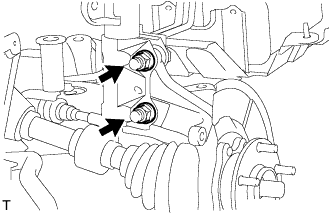 |
Remove the 2 bolts and 2 nuts, and disconnect the shock absorber from the steering knuckle.
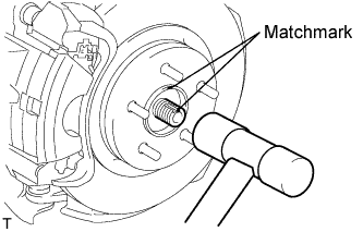 |
Put matchmarks on the drive shaft and the axle hub.
Using a plastic-faced hammer, remove the steering knuckle with axle hub.
| 62. DISCONNECT STEERING KNUCKLE WITH AXLE HUB RH |
| 63. DISCONNECT TIE ROD END SUB-ASSEMBLY LH |
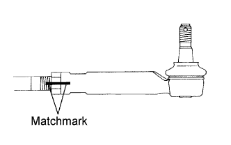 |
Put matchmarks on the tie rod end subassembly and rack end.
Remove the tie rod end sub-assembly and lock nut.
| 64. DISCONNECT TIE ROD END SUB-ASSEMBLY RH |
| 65. REMOVE FRONT DRIVE SHAFT ASSEMBLY LH |
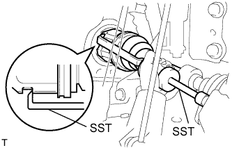 |
Using SST, remove the front drive shaft.
| 66. REMOVE FRONT DRIVE SHAFT ASSEMBLY RH |
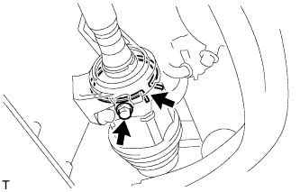 |
Squeeze the ends of the snap ring, and remove the snap ring from the bearing bracket.
Remove the bearing bracket bolt and front drive shaft from the bearing bracket.
| 67. REMOVE FRONT SUSPENSION MEMBER REINFORCEMENT LH |
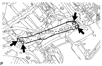 |
Remove the 4 bolts and front suspension member reinforcement.
| 68. REMOVE FRONT SUSPENSION MEMBER REINFORCEMENT RH |
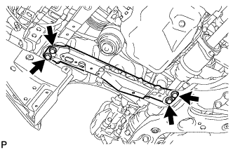 |
Remove the 4 bolts and front suspension member reinforcement.
| 69. REMOVE FRONT CROSSMEMBER SUB-ASSEMBLY |
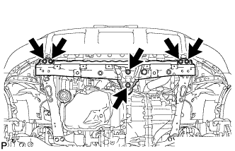 |
Remove the 6 bolts and front crossmember.
| 70. REMOVE FRONT ENGINE MOUNTING INSULATOR |
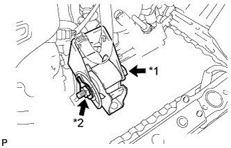 |
Remove the through bolt, nut and front engine mounting insulator.
| *1 | Through Bolt |
| *2 | Nut |
| 71. REMOVE FUEL HOSE PROTECTOR |
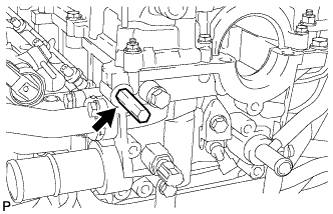 |
Remove the fuel hose protector from the cylinder head.
| 72. REMOVE ENGINE WITH TRANSAXLE |
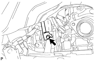 |
Remove the bolt and disconnect the cable bracket.
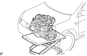 |
Set an engine lifter underneath the engine.
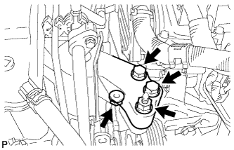 |
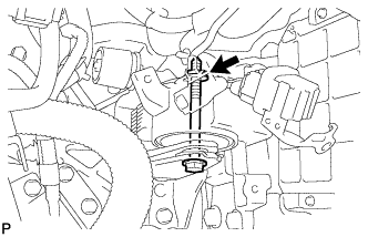
Remove the 2 bolts and 2 nuts, and disconnect the engine mounting insulator RH.
 |
Remove the bolt and nut, and disconnect the engine mounting insulator LH.
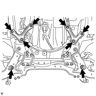 |
Remove the 6 bolts and front suspension member rear brace RH and LH.
Remove the 2 bolts and disconnect the suspension crossmember from the vehicle body.
Carefully remove the engine with transaxle from the vehicle.
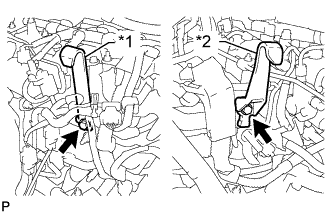 |
Install 2 engine hangers with 2 bolts as shown in the illustration.
| *1 | No. 1 Engine Hanger |
| *2 | No. 2 Engine Hanger |
| No. 1 engine hanger | 12281-26040 |
| No. 2 engine hanger | 12282-26010 |
| Bolt | 90105-81025 or 90105-W0042 |
Attach an engine sling device and hang the engine with a chain block.
| 73. REMOVE FRONT SUSPENSION CROSSMEMBER SUB-ASSEMBLY |
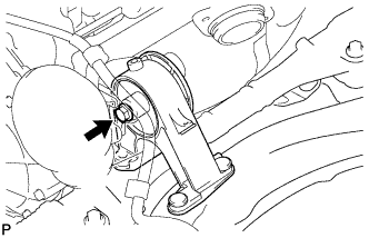 |
Remove the bolt and front suspension crossmember from the engine.
| 74. REMOVE REAR ENGINE MOUNTING INSULATOR |
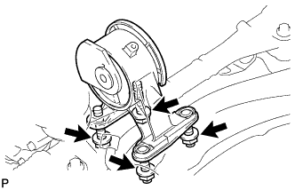 |
Remove the 2 bolts, 2 nuts and rear engine mounting insulator.
| 75. REMOVE NO. 1 AIR TUBE |
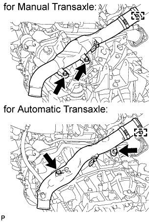 |
Loosen the hose clamp.
Remove the 2 bolts and No. 1 air tube.
| 76. REMOVE STARTER ASSEMBLY |
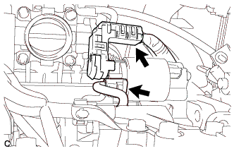 |
Disconnect the starter connector.
Open the terminal cap, remove the nut and disconnect the starter wire.
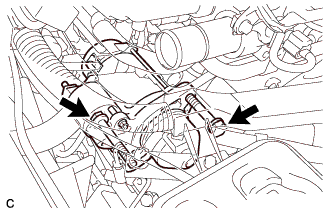 |
Remove the 2 bolts and starter.
| 77. REMOVE ENGINE WIRE |
Disconnect the connectors and detach the clamps securing the engine wire to the engine, and then remove the bracket bolts and engine wire from the engine.
| 78. REMOVE FRONT ENGINE MOUNTING BRACKET (for Manual Transaxle) |
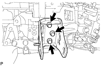 |
Remove the 3 bolts and front engine mounting bracket.
| 79. REMOVE FRONT ENGINE MOUNTING BRACKET (for Automatic Transaxle) |
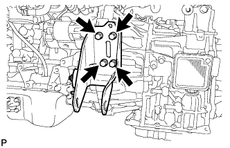 |
Remove the 4 bolts and front engine mounting bracket.
| 80. REMOVE REAR ENGINE MOUNTING BRACKET |
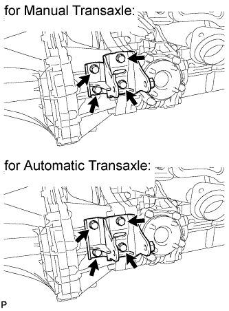 |
Remove the 4 bolts and rear engine mounting bracket.
| 81. REMOVE ENGINE MOUNTING BRACKET LH |
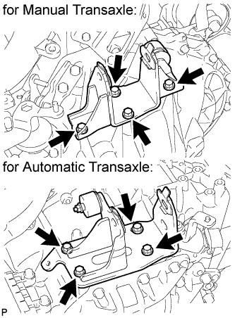 |
Remove the 4 bolts and engine mounting bracket.
| 82. REMOVE ENGINE MOUNTING INSULATOR LH |
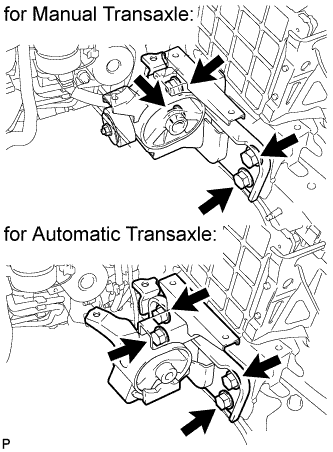 |
Remove the 4 bolts and engine mounting insulator.
| 83. REMOVE ENGINE MOUNTING INSULATOR RH |
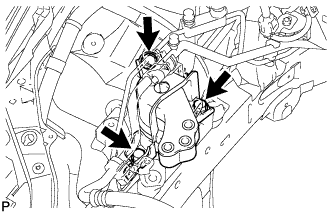 |
Remove the 3 bolts and engine mounting insulator.
| 84. REMOVE OIL PAN INSULATOR |
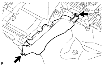 |
Remove the 2 bolts and oil pan insulator.
| 85. REMOVE STIFFENER PLATE RH |
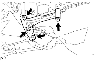 |
Remove the 4 bolts and stiffener plate RH.
| 86. REMOVE STIFFENER PLATE LH |
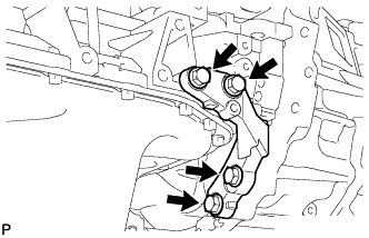 |
Remove the 4 bolts and stiffener plate LH.
| 87. REMOVE MANUAL TRANSAXLE ASSEMBLY (for Manual Transaxle) |
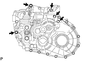 |
Remove the 5 bolts.
Separate and remove the transaxle from the engine.
| 88. REMOVE AUTOMATIC TRANSAXLE ASSEMBLY (for Automatic Transaxle) |
Remove the automatic transaxle (Click here).
| 89. REMOVE CLUTCH COVER ASSEMBLY (for Manual Transaxle) |
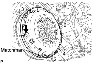 |
Align the matchmarks on the clutch cover and flywheel.
Loosen each set bolt 180°at a time until the spring tension is released.
Remove the set bolts, and pull off the clutch cover.
| 90. REMOVE CLUTCH DISC ASSEMBLY (for Manual Transaxle) |
| 91. REMOVE FLYWHEEL SUB-ASSEMBLY (for Manual Transaxle) |
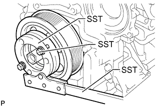 |
Using SST, hold the crankshaft pulley.
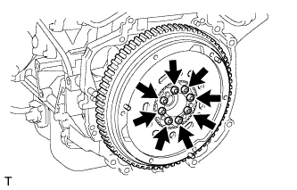 |
Using a T55 "TORX" socket wrench, remove the 8 bolts and flywheel.
| 92. REMOVE DRIVE PLATE AND RING GEAR SUB-ASSEMBLY (for Automatic Transaxle) |
|
Hold the crankshaft pulley with SST.
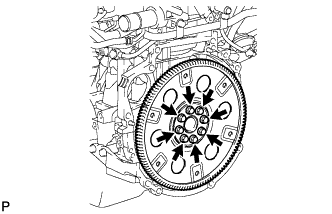 |
Remove the 8 bolts, rear drive plate spacer, drive plate and ring gear and front drive plate spacer.
| 93. INSTALL ENGINE TO ENGINE STAND |
Install the engine to an engine stand, and remove the sling device and chain block from the engine.
Remove the 2 bolts and No. 1 and No. 2 engine hangers.