DTC P0791 Intermediate Shaft Speed Sensor "A" Circuit |
DTC P0793 Intermediate Shaft Speed Sensor "A" |
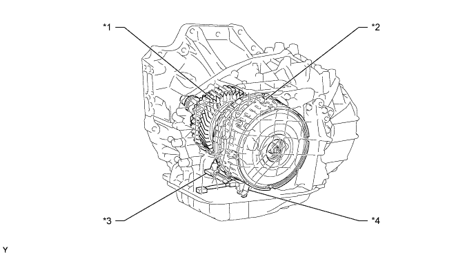
| *1 | Counter Gear | *2 | Clutch Drum |
| *3 | Speed Sensor NC | *4 | Speed Sensor NT |
| DTC Code | DTC Detection Condition | Trouble Area |
| P0791 | When the speed sensor input voltage is either higher than 1.9 V or below 0.1 V for 2 seconds or more (1-trip detection logic). |
|
| P0793 | When the vehicle speed is 25 km/h (15.5 mph) or more, the counter gear speed is less than 300 rpm for 2 seconds or more (1-trip detection logic). |
| DATA LIST |
Warm up the engine.
Turn the ignition switch off.
Connect the intelligent tester to the DLC3.
Turn the ignition switch to ON.
Turn the intelligent tester on.
Enter the following menus: Powertrain / ECT / Data List.
According to the display on the tester, read the Data List.
| Tester Display | Measurement Item/Range | Normal Condition | Diagnostic Note |
| SPD (NC) | Counter gear speed (speed sensor NC)/ Min.: 0 rpm Max.: 12750 rpm | Vehicle stopped: 0 km/h (0 mph) | The data is displayed in increments of 50 rpm. |
| NC Sensor Voltage | Counter gear speed sensor (speed sensor NC) output voltage/ Min.: 0 V Max.: 5 V | Engine idling: 0.1 to 1.9 V | - |
| 1.INSPECT SPEED SENSOR NC INSTALLATION |
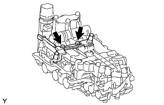 |
Make sure that the connector is properly connected, and check the speed sensor installation.
|
| ||||
| OK | |
 |
| 2.INSPECT TRANSMISSION WIRE |
 |
Disconnect the speed sensor connector.
Remove the TCM.
Measure the resistance according to the value(s) in the table below.
| Tester Connection | Condition | Specified Condition |
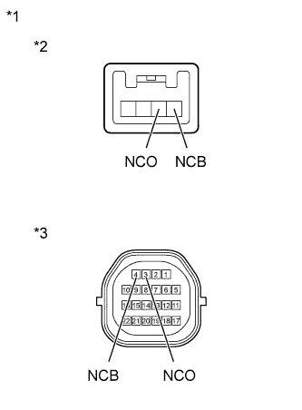
| NCB speed sensor side - 4 (NCB) TCM side | Always | Below 1 Ω |
| NCO speed sensor side - 3 (NCO) TCM side | Always | Below 1 Ω |
| NCB speed sensor side - Body ground | Always | 10 kΩ or higher |
| NCO speed sensor side - Body ground | Always | 10 kΩ or higher |
| NCB speed sensor side - All other terminals except 4 (NCB) TCM side | Always | 10 kΩ or higher |
| NCO speed sensor side - All other terminals except 3 (NCO) TCM side | Always | 10 kΩ or higher |
| *1 | Transmission Wire |
| *2 | Speed Sensor Side |
| *3 | TCM Side |
|
| ||||
| OK | |
|
| 3.REPLACE SPEED SENSOR NC (SPEED SENSOR) |
Replace the speed sensor (Click here).
| NEXT | |
|
| 4.CHECK IF DTC OUTPUT RECURS (DTC P0791 OR P0793) |
Connect the intelligent tester to the DLC3.
Turn the ignition switch to ON.
Turn the intelligent tester on.
Enter the following menus: Powertrain / ECT / DTC / Clear.
Perform the monitor drive pattern (Click here).
Enter the following menus: Powertrain / ECT / DTC.
Read the DTCs using the intelligent tester.
| Result | Proceed to |
| Only P0791 or P0793 is output | A |
| DTCs are not output | B |
|
| ||||
| A | ||
 | ||
| ||
