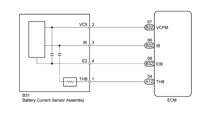
DTC P1550 Battery Current Sensor Circuit |
DTC P1551 Battery Current Sensor Circuit Low |
DTC P1552 Battery Current Sensor Circuit High |
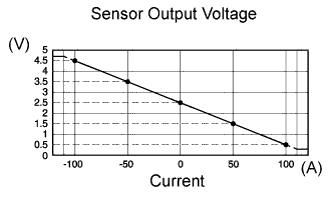
| DTC No. | DTC Detection Condition | Trouble Area |
| P1550 | The following condition continues for 10 seconds or more with the ignition switch ON (1 trip detection logic):
|
|
| P1551 | The battery current sensor output value is 0.2 V or less for 0.5 seconds or more with the ignition switch ON (1 trip detection logic). |
|
| P1552 | The battery current sensor output value is 4.8 V or higher for 0.5 seconds or more with the ignition switch ON (1 trip detection logic). |
|
| 1.INSPECT BATTERY CURRENT SENSOR ASSEMBLY |
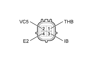 |
Disconnect the battery current sensor connector.
Measure the resistance according to the value(s) in the table below.
| Tester Connection | Condition | Specified Condition |
| 2 (VC5) - 4 (E2) | Always | 0.1 to 10 kΩ |
| 2 (VC5) - 3 (IB) | Always | Below 0.5 kΩ |
| 3 (IB) - 4 (E2) | Always | 0.05 to 10 kΩ |
| *1 | Component without harness connected (Battery Current Sensor Assembly) |
|
| ||||
| OK | |
 |
| 2.CHECK HARNESS AND CONNECTOR (BATTERY CURRENT SENSOR - ECM) |
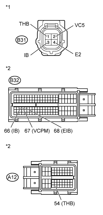 |
Disconnect the battery current sensor connector.
Disconnect the ECM connectors.
Measure the resistance according to the value(s) in the table below.
| Tester Connection | Condition | Specified Condition |
| B31-3 (IB) - B32-66 (IB) | Always | Below 1 Ω |
| B31-2 (VC5) - B32-67 (VCPM) | Always | Below 1 Ω |
| B31-4 (E2) - B32-68 (EIB) | Always | Below 1 Ω |
| B31-1 (THB) - A12-54 (THB) | Always | Below 1 Ω |
| Tester Connection | Condition | Specified Condition |
| B31-3 (IB) or B32-66 (IB) - Body ground | Always | 10 kΩ or higher |
| B31-2 (VC5) or B32-67 (VCPM) - Body ground | Always | 10 kΩ or higher |
| B31-1 (THB) or A12-54 (THB) - Body ground | Always | 10 kΩ or higher |
| *1 | Front view of wire harness connector (to Battery Current Sensor Assembly) |
| *2 | Front view of wire harness connector (to ECM) |
|
| ||||
| OK | ||
 | ||
| ||
