FRONT SUSPENSION LOWER NO. 1 ARM > INSTALLATION |
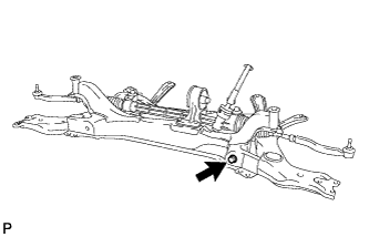
| 1. TEMPORARILY INSTALL FRONT SUSPENSION LOWER NO. 1 ARM SUB-ASSEMBLY LH |
|
Temporarily install the lower arm with the bolt and nut to the front side.
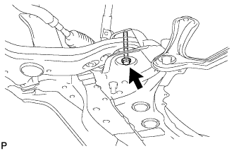 |
Temporarily install the lower arm with the bolt and nut to the rear side.
| 2. TEMPORARILY INSTALL FRONT SUSPENSION LOWER NO. 1 ARM SUB-ASSEMBLY RH |
| 3. CONNECT FRONT SUSPENSION CROSSMEMBER SUB-ASSEMBLY |
Slowly raise the crossmember jack, and connect the crossmember to the body.
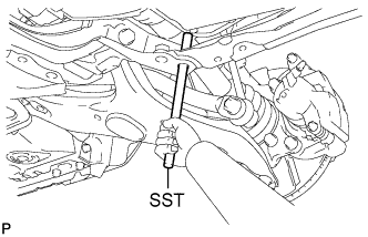 |
Using SST, align the holes of the suspension member and body.
Perform the procedure above on the other side.
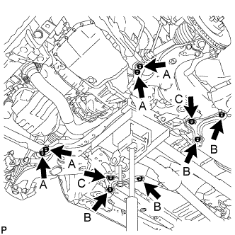 |
Install the member reinforcement with the 4 bolts labeled A.
Install the suspension member brace with the 6 bolts labeled B and C.
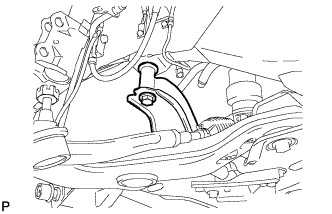 |
Install the suspension member with the bolt to the body.
Perform the procedure above on the other side.
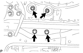 |
Install the engine mounting insulator rear with the 2 nuts and 2 bolts.
| 4. INSTALL FRONT STABILIZER LINK ASSEMBLY LH |
Install the link with the 2 nuts.
| 5. CONNECT FRONT SUSPENSION LOWER NO. 1 ARM SUB-ASSEMBLY LH |
Connect the lower arm with the 2 bolts and nut to the ball joint.
| 6. INSTALL FRONT WHEEL |
| 7. STABILIZE SUSPENSION |
Lower the vehicle.
Press down on the vehicle several times to stabilize the suspension.
| 8. TIGHTEN FRONT SUSPENSION CROSSMEMBER SUB-ASSEMBLY |
|
Tighten the bolts and nuts.
| 9. TIGHTEN FRONT SUSPENSION LOWER NO. 1 ARM SUB-ASSEMBLY LH |
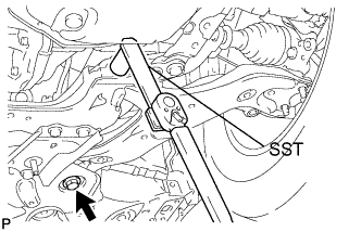 |
Using SST, and tighten the bolt on the front side.
Fix the nut in place and tighten the bolt on the rear side.
| 10. TIGHTEN FRONT SUSPENSION LOWER NO. 1 ARM SUB-ASSEMBLY RH |
| 11. INSTALL HOOD SUB-ASSEMBLY |
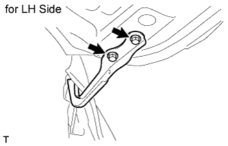 |
Install the hood with the 4 bolts.
Adjust the hood position (Click here).
| 12. INSPECT AND ADJUST HOOD SUB-ASSEMBLY |
|
Adjust the hood's position.
Loosen the hood's 4 hinge bolts.
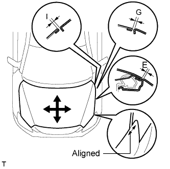 |
Move the hood and adjust the clearance between the hood and front fender. Make sure that the clearance is within the standard range.
| Area | Specified Condition |
| E | 3.5 +- 1.5 mm (0.138 +- 0.059 in.) |
| G | 3.5 +- 1.5 mm (0.138 +- 0.059 in.) |
| I | 3.5 +- 1.5 mm (0.138 +- 0.059 in.) |
Tighten the hood's 4 hinge bolts after the adjustment.
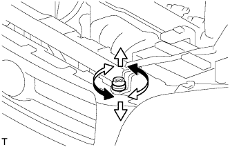 |
Adjust the cushion rubber so that the height of the hood and fender are aligned.
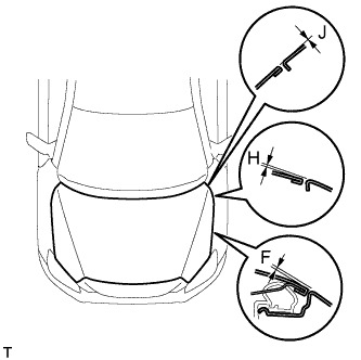 |
Raise or lower the hood's front end by turning the cushion rubber. Make sure that the clearance is within the standard range.
| Area | Specified Condition |
| F | 0.6 +- 1.5 mm (0.024 +- 0.059 in.) |
| H | 0.5 +- 1.5 mm (0.020 +- 0.059 in.) |
| J | 0.0 +- 1.5 mm (0.000 +- 0.059 in.) |
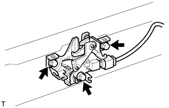 |
Adjust the hood lock.
Loosen the 3 bolts.
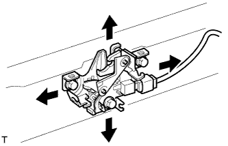 |
Adjust the hood lock position so that the striker can enter it smoothly.
Tighten the 3 bolts after the adjustment.
| 13. INSPECT AND ADJUST FRONT WHEEL ALIGNMENT |
Inspect and adjust the front wheel alignment (Click here).