Home › BRAKE › BRAKE CONTROL › ANTI-LOCK BRAKE SYSTEM

DTC    C0278/11    Open in ABS Solenoid Relay Circuit

DTC    C0279/12    Short to B+ in ABS Solenoid Relay Circuit

for Preparation Click here


DESCRIPTION

The solenoid relay supplies power to the ABS solenoid.
After the ignition switch is turned on, the vehicle speed has reached 6 km/h (4 mph) and the solenoid is determined to be normal by the initial check self-diagnosis, the relay switches on. If open circuit is detected, the relay switches off.
These DTCs may be set if the voltage supply to the solenoid relay (+BS) falls below the DTC detection threshold due to the battery or alternator outputs being insufficient.

DTC No.
DTC Detection Condition
Trouble Area
C0278/11
When either condition below is met:
  1. Both of following conditions continue for 0.2 seconds or more.
    1. IG1 terminal voltage between 9.5 V and 18.5 V.
    2. Solenoid relay contact open when relay on.
  2. Both of following conditions continue for 0.2 seconds or more.
    1. IG1 terminal voltage becomes lower than 9.5 V when relay turned on.
    2. Relay contact remains open.
  1. ABS2 fuse
  2. Harness or connector (+BS circuit)
  3. Brake actuator (Skid control ECU)
C0279/12
Immediately after ignition switch turned on, solenoid relay contact closed for 0.2 seconds or more when relay off.
  1. ABS2 fuse
  2. Harness or connector (+BS circuit)
  3. Brake actuator (Skid control ECU)

HINT:
C0278/11 and C0279/12: The skid control ECU begins to detect these DTCs when the vehicle speed exceeds 6 km/h (4 mph).


WIRING DIAGRAM

Refer to DTC C0226/21, C0236/22, C0246/23, C0256/24 .

INSPECTION PROCEDURE

1.INSPECT FUSE (ABS2)
  1. Remove the ABS2 fuse from the engine room No. 1 relay block.

  1. Measure the resistance of the fuse.

    Standard resistance:
    Below 1 Ω


NG
REPLACE FUSE
OK


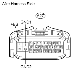
2.CHECK WIRE HARNESS (SKID CONTROL ECU - BATTERY AND BODY GROUND)


    C117862E07
  1. Disconnect the A27 ECU connector.

  1. Measure the voltage of the wire harness side connector.

    Standard voltage:
    Tester Connection
    Specified Condition
    A27-1 (+BS) - Body ground
    11 to 14 V

  1. Measure the resistance of the wire harness side connector.

    Standard resistance:
    Tester Connection
    Specified Condition
    A27-2 (GND1) - Body ground
    Below 1 Ω
    A27-24 (GND2) - Body ground
    Below 1 Ω


NG
REPAIR OR REPLACE HARNESS AND CONNECTOR
OK


3.RECONFIRM DTC
  1. Clear the DTCs (Click here).

  1. Start the engine.

  1. Drive the vehicle at 6 km/h (4 mph) or more to activate the initial check.

  1. Check if the same DTC(s) is output (Click here).
    Result 
    Result
    Proceed to
    DTC is output
    A
    DTC is not output
    B


B
USE SIMULATION METHOD TO CHECK (Click here)
A

REPLACE BRAKE ACTUATOR ASSEMBLY (Click here)