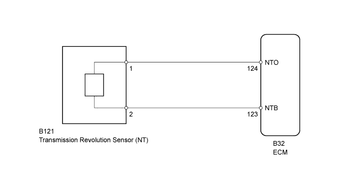
DTC P0715 Input/Turbine Speed Sensor "A" Circuit |
DTC P0717 Input/Turbine Speed Sensor "A" Circuit No Signal |
| DTC Code | DTC Detection Condition
| Trouble Area |
| P0715 |
|
|
| P0717 |
|
|
| 1.READ VALUE USING INTELLIGENT TESTER (SPD (NT) AND NT SENSOR VOLTAGE) |
Connect the intelligent tester to the DLC3.
Turn the ignition switch to ON.
Turn the intelligent tester on.
Enter the following menus: Powertrain / Engine and ECT / Data List.
In accordance with the display on the tester, read the Data List.
| Tester Display | Measurement Item/Range | Normal Condition | Diagnostic Note |
| SPD (NT) | Input turbine speed/ min.: 0 rpm max.: 12750 rpm |
| Data is displayed in increments of 50 rpm. |
| NT Sensor Voltage | Input turbine speed (NT) sensor output voltage/ min.: 0 V max.: 5 V | Engine idling (Vehicle stopped with shift lever in P or N): Constantly changes between 0.8 to 1.6 V and 2.4 to 3.2 V | - |
| Result | Proceed to |
| Data displayed is not as specified under Normal Condition | A |
| Data displayed is as specified under Normal Condition | B |
|
| ||||
| A | |
 |
| 2.INSPECT TRANSMISSION REVOLUTION SENSOR (NT) |
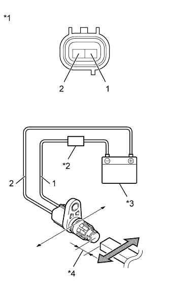 |
Remove the transmission revolution sensor (NT) (Click here).
Connect the battery to the sensor as shown in the illustration.
Wave a magnetic object left and right in front of the transmission revolution sensor (NT) tip (5 mm (0.197 in.) gap or closer) to change the high/low signals while measuring the current.
Measure the current according to the value(s) in the table below.
| Tester Connection | Condition | Specified Condition |
| 1 - 2 | Low signal | 4 to 8 mA |
| 1 - 2 | High signal | 12 to 16 mA |
| *1 | Component without harness connected (Transmission Revolution Sensor (NT)) |
| *2 | Ammeter |
| *3 | Battery |
| *4 | 5 mm (0.197 in.) Gap or Closer |
|
| ||||
| OK | |
|
| 3.CHECK HARNESS AND CONNECTOR (TRANSMISSION REVOLUTION SENSOR (NT) - ECM) |
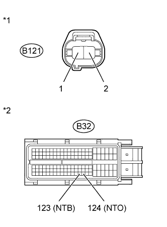 |
Disconnect the transmission revolution sensor (NT) connector.
Disconnect the ECM connector.
Measure the resistance according to the value(s) in the table below.
| Tester Connection | Condition | Specified Condition |
| B121-1 - B32-124 (NTO) | Always | Below 1 Ω |
| B121-2 - B32-123 (NTB) | Always | Below 1 Ω |
| B121-1 or B32-124 (NTO) - Body ground | Always | 10 kΩ or higher |
| B121-2 or B32-123 (NTB) - Body ground | Always | 10 kΩ or higher |
| *1 | Front view of wire harness connector (to Transmission Revolution Sensor (NT)) |
| *2 | Front view of wire harness connector (to ECM) |
|
| ||||
| OK | |
|
| 4.REPLACE ECM |
Replace the ECM (Click here).
| NEXT | |
|
| 5.PERFORM INITIALIZATION |
| Replaced Part |
|
Using the intelligent tester, perform reset memory, deceleration sensor 0 point calibration and CVT oil pressure calibration (Click here).
Check that no DTC is stored.
| NEXT | ||
 | ||
| ||
| 6.REPLACE ECM |
Replace the ECM (Click here).
| NEXT | |
|
| 7.PERFORM INITIALIZATION |
| Replaced Part |
|
Using the intelligent tester, perform reset memory, deceleration sensor 0 point calibration and CVT oil pressure calibration (Click here).
Check that no DTC is stored.
| NEXT | ||
| ||
| ||

