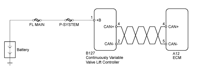
DTC U011B Lost Communication with Rocker Arm Control Module "A" |
| DTC No. | DTC Detection Condition | Trouble Area |
| U011B | CAN communication stops (1 trip detection logic). |
|
| Actuator position learning is performed when these DTCs are stored. |
| P1046, P1049, P104A, P1055, P2646, P2647, P2648, P2649, P264A, U011B |
| 1.CHECK CONTINUOUSLY VARIABLE VALVE LIFT CONTROLLER ASSEMBLY (POWER SOURCE) |
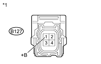 |
Disconnect the continuously variable valve lift controller assembly connector.
Measure the voltage according to the value(s) in the table below.
| Tester Connection | Switch Condition | Specified Condition |
| B127-1 (+B) - Body ground | Ignition switch ON | 11 to 14 V |
| *1 | Component without harness connected (Continuously Variable Valve Lift Controller) |
Reconnect the continuously variable valve lift controller assembly connector.
|
| ||||
| OK | |
 |
| 2.CHECK HARNESS AND CONNECTOR (CONTINUOUSLY VARIABLE VALVE LIFT CONTROLLER - ECM) |
Disconnect the continuously variable valve lift controller assembly connector.
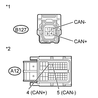 |
Disconnect the ECM connector.
Measure the resistance according to the value(s) in the table below.
| Tester Connection | Switch Condition | Specified Condition |
| B127-4 (CAN+) - A12-4 (CAN+) | Ignition switch off | Below 1 Ω |
| B127-2 (CAN-) - A12-5 (CAN-) | Ignition switch off | Below 1 Ω |
| Tester Connection | Switch Condition | Specified Condition |
| B127-4 (CAN+) or A12-4 (CAN+) - Body ground | Ignition switch off | 10 kΩ or higher |
| B127-2 (CAN-) or A12-5 (CAN-) - Body ground | Ignition switch off | 10 kΩ or higher |
| *1 | Front view of wire harness connector (to Continuously Variable Valve Lift Controller) |
| *2 | Front view of wire harness connector (to ECM) |
Reconnect the ECM connector.
Reconnect the continuously variable valve lift controller assembly connector.
|
| ||||
| OK | |
|
| 3.REPLACE CONTINUOUSLY VARIABLE VALVE LIFT CONTROLLER ASSEMBLY |
Replace the continuously variable valve lift controller assembly (Click here).
| NEXT | |
|
| 4.PERFORM SIMULATION TEST |
Connect the intelligent tester to the DLC3.
Turn the ignition switch to ON.
Turn the tester on.
Clear the DTC.
Perform a simulation test.
Turn the ignition switch to ON and wait 5 seconds
Start the engine and idle it for 5 seconds.
Turn the ignition switch off and wait 5 seconds
Turn the ignition switch to ON.
Turn the tester on.
Enter the following menus: Powertrain / Engine and ECT / DTC.
Read the DTCs.
| Result | Proceed to |
| DTC U011B is output | A |
| DTC is not output | B |
|
| ||||
| A | ||
 | ||
| ||
