2AR-FE INTAKE / EXHAUST INTAKE MANIFOLD REMOVAL
PROCEDURE

 1.REMOVE FUEL DELIVERY PIPE
2.DRAIN ENGINE COOLANT
3.REMOVE THROTTLE WITH MOTOR BODY ASSEMBLY
4.REMOVE WINDSHIELD WIPER MOTOR ASSEMBLY
5.REMOVE OUTER COWL TOP PANEL SUB-ASSEMBLY
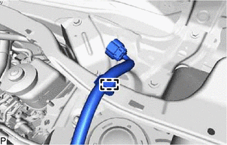
Detach the clamp and disconnect the wire harness from the outer cowl top panel sub-assembly.
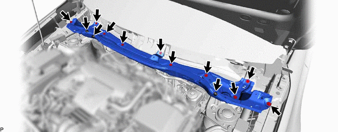
Remove the 13 bolts and outer cowl top panel sub-assembly.
6.REMOVE NO. 1 HOSE TO HOSE TUBE
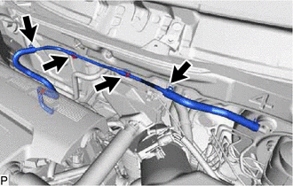
Slide the 2 clamps and disconnect the 2 hoses from the No. 1 hose to hose tube.
Remove the 2 nuts and No. 1 hose to hose tube.
7.DISCONNECT HEATER HOSE
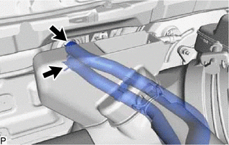
Slide the clamp and disconnect the inlet heater water hose from theheater radiator unit.
Slide the clamp and disconnect the outlet heater water hose from theheater radiator unit.
8.DISCONNECT WIRE HARNESS
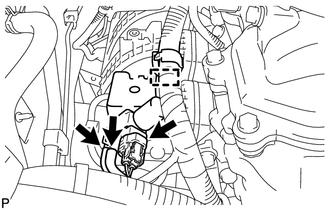
Disconnect the connector, detach the clamp and disconnect the 2 vacuum hoses, and then remove the vacuum switching valve.
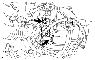
Detach the 2 clamps.
Remove the 2 bolts and wiring harness clamp bracket.
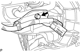
Remove the bolt and disconnect the bracket.
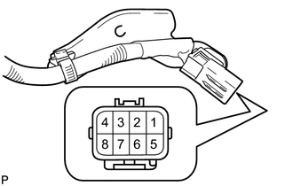
| *a | Component without harness connected
(Tumble Control Valve) |
Apply battery voltage to the terminals of the connector to close the tumble control valves.
- Standard:
Tester Connection Specified Condition Positive (+) battery voltage applied to terminal 8 (M-), and negative (-) battery voltage applied to terminal 4 (M+) Open → Closed
- NOTICE:
- ·
If this procedure is not performed, the valves may be damaged when the intake manifold is removed.
·Apply battery voltage for 1 to 3 seconds.
·If battery voltage is applied for more than 3 seconds, the actuator may be damaged.
·Do not allow the lead wires to contact the other terminals.
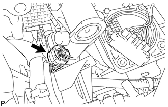
Disconnect the intake air control valve actuator connector.
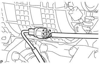
Detach the clamp and disconnect the wire harness.
9.DISCONNECT NO. 2 PCV HOSE
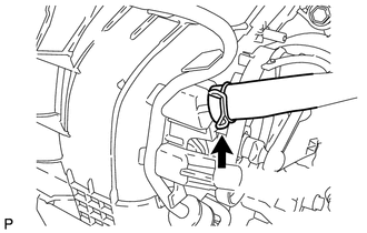
Slide the clamp and disconnect the No. 2 PCV hose from the intake manifold.
10.REMOVE INTAKE MANIFOLD
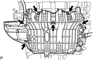
Remove the 6 bolts and intake manifold.
- NOTICE:
-
The valves may be damaged if they are not closed before removing the intake manifold.
Remove the gasket from the intake manifold.
Remove the 2 vacuum hoses from the intake manifold.
11.REMOVE UNION TO CONNECTOR TUBE HOSE
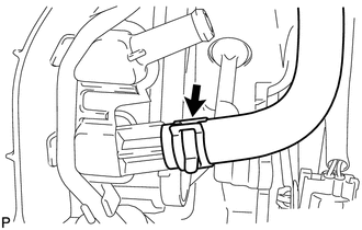
Slide the clamp and remove the union to connector tube hose from the intake manifold.
12.REMOVE CHECK VALVE
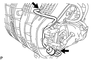
Disconnect the 2 vacuum hoses from the intake manifold and remove the check valve.
Remove the 2 vacuum hoses from the check valve.
13.REMOVE PURGE LINE HOSE
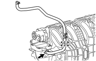
Disconnect the purge line hose from the clamp.
Slide the clamp and remove the purge line hose from the intake manifold.
14.REMOVE INTAKE AIR CONTROL VALVE ACTUATOR (for TCV)