AXLE AND DIFFERENTIAL FRONT AXLE HUB REMOVAL
CAUTION / NOTICE / HINT
- HINT:
- ·
Use the same procedure for the RH and LH sides.
·The procedure listed below is for the LH side.
PROCEDURE

 1.REMOVE FRONT WHEEL
2.REMOVE FRONT AXLE SHAFT NUT LH
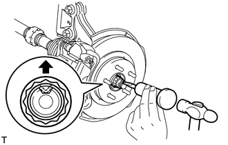
Using SST and a hammer, unstake the staked part of the front axle shaft nut.
- SST
- 09930-00010 (09931-00010, 09931-00020)
- NOTICE:
-
Loosen the staked part of the front axle shaft nut completely, otherwise the screw of the drive shaft may be damaged.
While applying the brakes, remove the front axle shaft nut.
3.DISCONNECT FRONT SPEED SENSOR LH
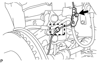
Remove the bolt and clamp, and disconnect the front speed sensor.
- NOTICE:
-
Be sure to disconnect the front speed sensor from the front shock absorber with coil spring completely.
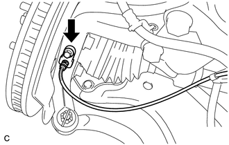
Remove the bolt and disconnect the front speed sensor from the steering knuckle.
- NOTICE:
- ·
Prevent foreign matter from attaching to the sensor tip.
·Be careful not to damage the front speed sensor.
·Clean the installation hole and the surface for the speed sensor every time the speed sensor is removed.
4.DISCONNECT FRONT FLEXIBLE HOSE
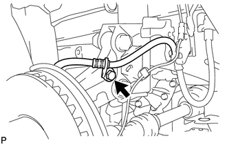
Remove the bolt and disconnect the flexible hose.
5.DISCONNECT FRONT DISC BRAKE CALIPER ASSEMBLY LH
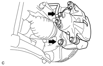
Remove the 2 bolts and disconnect the front disc brake caliper assembly from the steering knuckle.
- NOTICE:
-
Use wire or an equivalent tool to keep the brake caliper from hanging down by the flexible hose.
6.REMOVE FRONT DISC
Click hereBrake>BRAKE (FRONT)>FRONT BRAKE>REMOVAL
7.DISCONNECT TIE ROD END SUB-ASSEMBLY LH
8.DISCONNECT FRONT LOWER NO. 1 SUSPENSION ARM SUB-ASSEMBLY LH
9.REMOVE FRONT AXLE ASSEMBLY LH
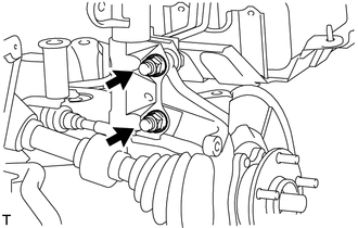
Remove the 2 bolts and 2 nuts, and disconnect the front shock absorber assembly with coil spring from the steering knuckle.
- HINT:
-
While fixing the nuts in place, loosen and remove the bolts.
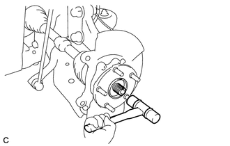
| *a | Matchmark |
Put matchmarks on the drive shaft and front axle hub sub-assembly.
Using a plastic-faced hammer, remove the steering knuckle assembly.
- NOTICE:
-
Be careful not to damage the front axle outboard joint boot and speed sensor rotor. Do not excessively push out the drive shaft from the axle assembly.
10.REMOVE FRONT AXLE HUB SUB-ASSEMBLY LH
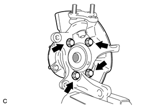
Secure the front axle assembly in a vise.
- NOTICE:
-
When using a vise, do not overtighten it.
Remove the 4 bolts and front axle hub sub-assembly from the steering knuckle.
- NOTICE:
-
Do not place the hub and bearing's magnet rotor side so that it is facing downward, and do not allow the magnet rotor side to become damaged or contact foreign matter.
Remove the front brake dust cover from the steering knuckle.