POWER ASSIST SYSTEMS POWER STEERING SYSTEM C1524/24 Motor Circuit Malfunction C1555/25 Motor Relay Welding Failure
DESCRIPTION
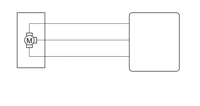
The power steering ECU assembly supplies current to the power steering motor assembly through the motor circuit.
| DTC No. | Detection Item | DTC Detection Condition | Trouble Area | Warning Indicate | Return-to-normal Condition |
|---|---|---|---|---|---|
| C1524/24 | Motor Circuit Malfunction | Short (or open) in motor circuit or abnormal voltage or current in motor circuit | ·
Power steering motor assembly ·
Power steering ECU assembly |
On | Ignition switch ON again |
| C1555/25 | Motor Relay Welding Failure | Motor relay circuit malfunction | ·
Power steering motor assembly ·
Power steering ECU assembly |
On | Ignition switch ON again |
WIRING DIAGRAM
CAUTION / NOTICE / HINT
- NOTICE:
-
If the power steering ECU assembly has been replaced, perform assist map writing (Click here Steering>POWER ASSIST SYSTEMS>POWER STEERING SYSTEM>CALIBRATION).
PROCEDURE
Disengage the 4 claws to remove the protector.
Click hereSteering>POWER ASSIST SYSTEMS>POWER STEERING ECU>REMOVAL
Check that the motor terminal bolts are tightened to the specified torque.
Click hereSteering>POWER ASSIST SYSTEMS>POWER STEERING ECU>INSTALLATION
- OK:
The motor terminal bolts are tightened to the specified torque.
- Result:
Proceed to OK NG
OK
NG
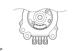
| *1 | Power Steering Motor Assembly |
Remove the power steering motor assembly.
Click hereSteering>STEERING COLUMN>STEERING COLUMN ASSEMBLY>DISASSEMBLY
Measure the resistance according to the value(s) in the table below.
- Standard Resistance:
Tester Connection Condition Specified Condition 1 (PHA) - 2 (PHB) 25°C (77°F) 12.7 to 17.2 mΩ 2 (PHB) - 3 (PHC) 25°C (77°F) 12.7 to 17.2 mΩ 3 (PHC) - 1 (PHA) 25°C (77°F) 12.7 to 17.2 mΩ 1 (PHA) - Motor case Always 10 kΩ or higher 2 (PHB) - Motor case Always 10 kΩ or higher 3 (PHC) - Motor case Always 10 kΩ or higher
- Result:
Proceed to OK NG
OK
NG
Turn the ignition switch off.
Connect the Techstream to the DLC3.
Start the engine.
Turn the Techstream on.
Enter the following menus: Chassis / EMPS / Data List.
Select the items "Motor Terminal Volt (U)", "Motor Terminal Volt (V)" and "Motor Terminal Volt (W)" in the Data List and read the value displayed on the Techstream.
- Chassis > EMPS > Data List
-
Tester Display Measurement Item Range Normal Condition Diagnostic Note Motor Terminal Volt(U) Motor terminal voltage (A phase) Min.: 0.000 V
Max.: 98.000 VEngine running and steering wheel being turned: Value changes within 4 to 35 V range - Motor Terminal Volt(V) Motor terminal voltage (B phase) Min.: 0.000 V
Max.: 98.000 VEngine running and steering wheel being turned: Value changes within 4 to 35 V range - Motor Terminal Volt(W) Motor terminal voltage (C phase) Min.: 0.000 V
Max.: 98.000 VEngine running and steering wheel being turned: Value changes within 4 to 35 V range -
- Chassis > EMPS > Data List
-
Tester Display Motor Terminal Volt(U) Motor Terminal Volt(V) Motor Terminal Volt(W) - 50003 142 22,23,24
- Result:
Result Proceed to During steering operation, value changes within 4 to 35 V range. A During steering operation, voltage is not generated. B
A
B