1AD-FTV FUEL FUEL SUPPLY PUMP INSTALLATION
CAUTION / NOTICE / HINT
- NOTICE:
- ·
When replacing the injector assemblies (including shuffling the injector assemblies between the cylinders), common rail assembly, intake manifold or cylinder head sub-assembly, it is necessary to replace the injection pipes with new ones.
·When replacing the fuel supply pump assembly, common rail assembly, intake manifold or cylinder head sub-assembly, it is necessary to replace the fuel inlet pipe sub-assembly with a new one.
PROCEDURE

 22100
1.INSTALL FUEL SUPPLY PUMP ASSEMBLY
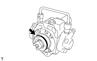
Apply a light coat of engine oil to a new O-ring.
Install the O-ring to the fuel supply pump assembly.
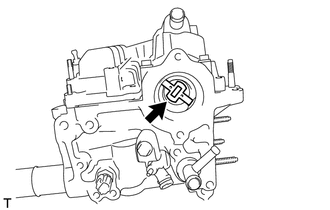
Install the No. 1 supply pump drive coupling.
- NOTICE:
-
When reusing the No. 1 supply pump drive coupling, it must be installed in the same orientation (top/bottom, front/back) as when it was removed.
- HINT:
-
Line up the No. 1 supply pump drive coupling with the groove in the camshaft end.
Install the fuel supply pump assembly with the 2 bolts.
- Torque:
- 21 N*m (209 kgf*cm, 15 ft.*lbf)
- HINT:
-
Line up the end of the supply pump drive shaft with the No. 1 supply pump drive coupling.
Connect the suction control valve connector.
Connect the fuel temperature sensor connector.
23901E
2.INSTALL FUEL TUBE SUB-ASSEMBLY
Temporarily install the fuel tube sub-assembly and 2 new gaskets with the check valve and union bolt.
Tighten the check valve.
- Torque:
- 32 N*m (321 kgf*cm, 23 ft.*lbf)
Tighten the union bolt.
- Torque:
- 23 N*m (235 kgf*cm, 17 ft.*lbf)
Connect the fuel tube sub-assembly.
Click hereEngine / Hybrid System>1AD-FTV FUEL>FUEL SYSTEM>PRECAUTION
Connect the exhaust fuel addition injector connector.
23292A
3.INSTALL FUEL HOSE PROTECTOR
23804C
4.INSTALL FUEL INLET PIPE SUB-ASSEMBLY
Temporarily install the fuel inlet pipe sub-assembly with the 2 No. 2 injection pipe clamps and nut.
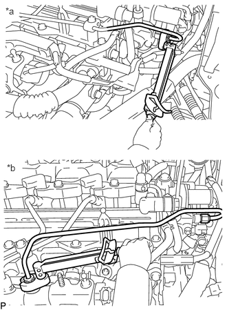
| *a | Fuel Supply Pump Assembly Side |
| *b | Common Rail Assembly Side |
Using a 14 mm union nut wrench, tighten the 2 fuel inlet pipe sub-assembly union nuts on the fuel supply pump assembly side.
- Torque:
- 30 N*m (306 kgf*cm, 22 ft.*lbf)
- NOTICE:
-
Use the formula to calculate special torque values for situations where a union nut wrench is combined with a torque wrench.
-
Click hereGeneral>INTRODUCTION>REPAIR INSTRUCTION>PRECAUTION
Using a 14 mm union nut wrench, tighten the 2 fuel inlet pipe sub-assembly union nuts on the common rail assembly side.
- Torque:
- 30 N*m (306 kgf*cm, 22 ft.*lbf)
- NOTICE:
-
Use the formula to calculate special torque values for situations where a union nut wrench is combined with a torque wrench.
-
Click hereGeneral>INTRODUCTION>REPAIR INSTRUCTION>PRECAUTION
Tighten the No. 2 injection pipe clamp nut.
- Torque:
- 5.0 N*m (51 kgf*cm, 44 in.*lbf)
23271H
5.CONNECT NO. 1 FUEL HOSE
Connect the No. 1 fuel hose to the fuel supply pump assembly, and slide the 2 clamps to secure it.
23274D
6.INSTALL NO. 3 FUEL HOSE
Install the No. 3 fuel hose to the No. 2 nozzle leakage pipe assembly and fuel supply pump assembly, and slide the 2 clamps to secure it.
7.INSTALL AIR CLEANER CASE
17801
8.INSTALL AIR CLEANER FILTER ELEMENT SUB-ASSEMBLY
17705
9.INSTALL AIR CLEANER CAP SUB-ASSEMBLY
10.CONNECT CABLE TO NEGATIVE BATTERY TERMINAL
- NOTICE:
-
When disconnecting the cable, some systems need to be initialized after the cable is reconnected.
-
Click hereGeneral>INTRODUCTION>REPAIR INSTRUCTION>INITIALIZATION
11.PERFORM INITIALIZATION
12.BLEED AIR FROM FUEL SYSTEM
13.INSPECT FOR FUEL LEAK
12611
14.INSTALL NO. 1 ENGINE COVER